Stator of electric rotating machine

a rotating machine and stator technology, applied in the direction of dynamo-electric machines, electrical equipment, magnetic circuit shapes/forms/construction, etc., can solve the problems of excessive magnetic loss of the stator, inability to precisely achieve the desired value of the clamping margin, and inability to assemble the stator coil of a cylindrical cage shape into a stator core of a rigid core shape, etc., to achieve the effect of preventing stress and large manufacturing tolerance of components

Active Publication Date: 2011-03-22
DENSO CORP
View PDF5 Cites 4 Cited by
  • Summary
  • Abstract
  • Description
  • Claims
  • Application Information

AI Technical Summary

Benefits of technology

[0026]The present invention allows large manufacturing tolerance of the components of a stator having a core assembly body including a stator core and phase windings, and an outer casing into which the core assembly body is fitted, while preventing the stress between the core assembly body and the outer casing from becoming exceedingly large.

Problems solved by technology

However, it is exceedingly difficult to assemble the stator coil of a cylindrical cage shape into a stator core of a rigid core shape.
However, since the components of the stator are manufactured with some manufacturing tolerance, it is not possible to exactly achieve the desired value of the clamping margin.
When the manufacturing tolerance is set larger, although the components can be manufactured easily, the following problems occur.
If the clamping margin becomes large due to the large manufacturing tolerance, since the stress between the ring assembly of the core pieces and the outer casing becomes larger than necessary, and the core pieces are applied with excessively large clamping force at their abutting portions in the circumferential direction, magnetic loss of the stator may excessively increase.
In addition, in this case, there occur other problems including deformation, variation of the diameter, and degradation of the roundness of the ring assembly of the core pieces.
Furthermore, when the manufacturing tolerance is large, since the variation of the stress between the ring assembly of the core pieces and the outer casing becomes large, the stator-to-stator performance (magnetic loss) variation becomes large.

Method used


Image

  • Stator of electric rotating machine
  • Stator of electric rotating machine
  • Stator of electric rotating machine

Examples


first embodiment

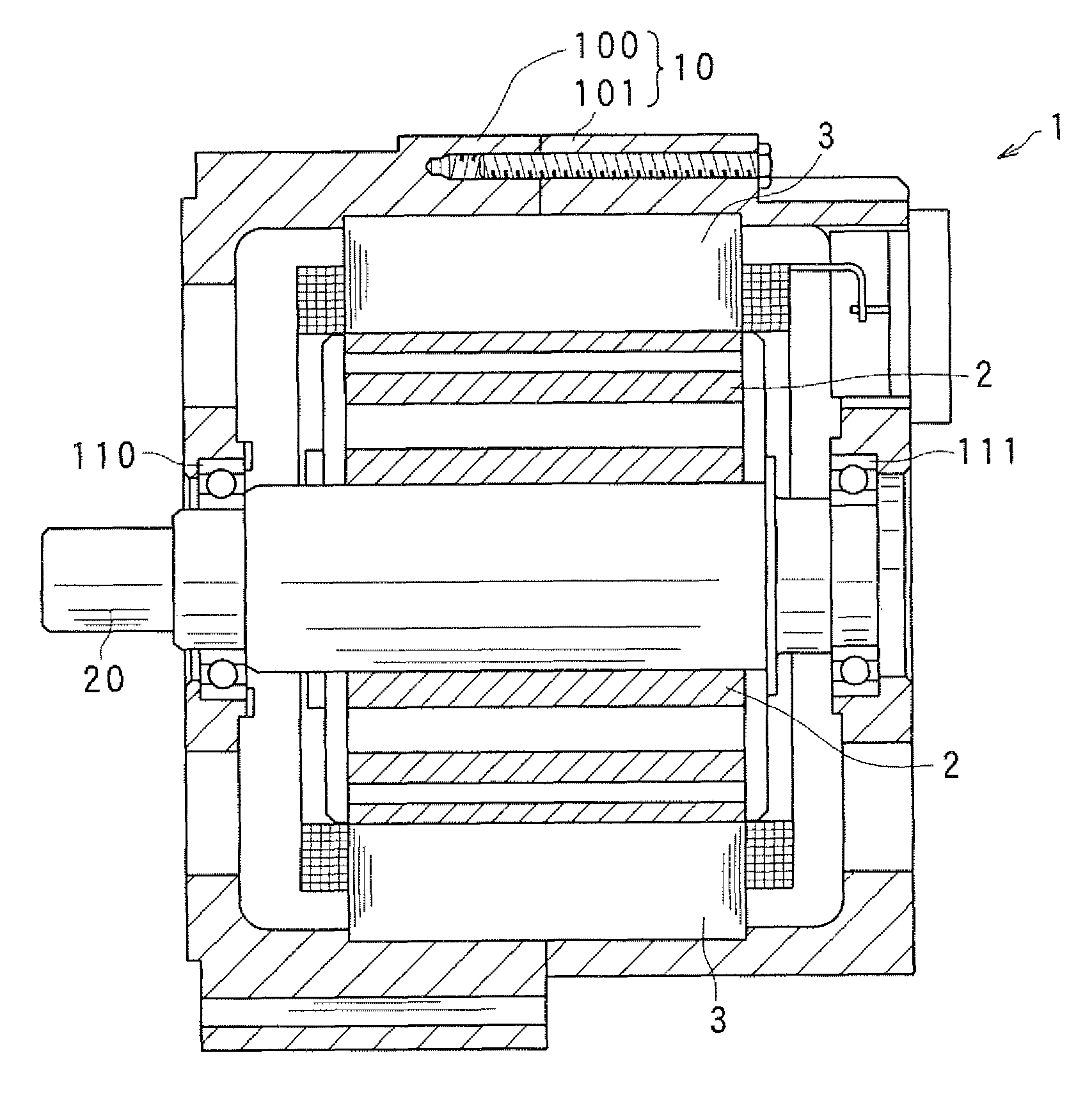
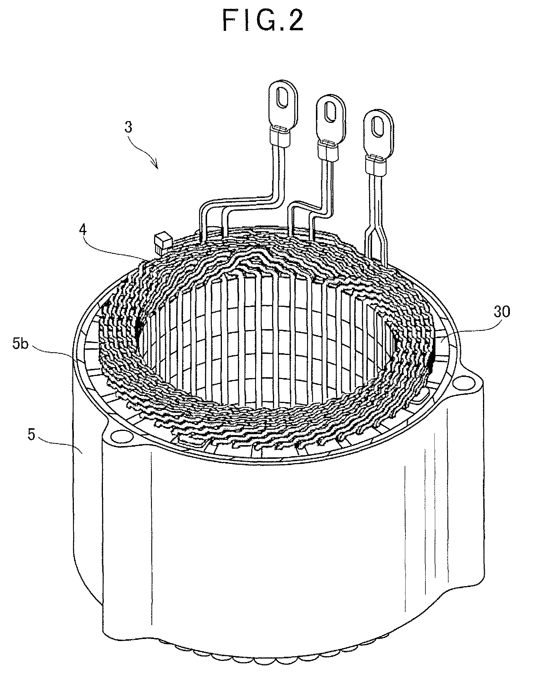
[0044]FIG. 1 is an axial cross-sectional view showing a structure of an electric rotating machine 1 including a stator according to a first embodiment of the invention.

[0045]As shown in this figure, the electric rotating machine 1 includes a housing 10 constituted by a pair of housing members 100 and 101 each having a bottomed tubular shape and joined to each other at their opening portions, a rotor 2 fixed to a rotating shaft 20 retractably supported by the housing 10 through bearings 110 and 111, and a stator 3 fixed to the housing 10 so as to surround the rotor 2 inside the housing 10.

[0046]The rotor 2 is provided with a plurality of magnet poles (S poles and N poles) formed in the outer periphery of the rotor 2 facing the inner periphery of the stator 3, such that different poles alternate in the circumferential direction of the rotor 2. In this embodiment, an 8-pole (four N poles and four S poles) rotor is used as the rotor 2.

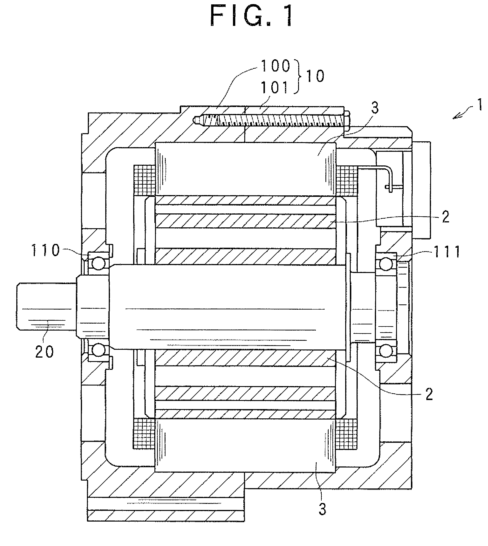
[0047]As shown in FIG. 2, the stator 3 includes a st...

second embodiment

[0090]In the above described first embodiment, the gaps between the core assembly body 50 and the outer casing 5 are provided in the forms of the slits 5b. However, the present invention is not limited thereto. In the below described second embodiment, the gaps are formed by the shape of the outer periphery of the core assembly body 50.

[0091]FIG. 15 is a plan view showing the shape of one of core pieces 2032 in the second embodiment.

[0092]The stator core of the second embodiment is constituted of a predetermined number of (twenty four in this embodiment) the core pieces 2032 joined in a ring. Each core piece 2032 defines one slot 2031, and another slot 2031 with the circumferentially adjacent slot 2032. The core piece 2032 is constituted including a pair of tooth portions 2320 extending radially inwardly, and a back core portion 2321 connecting these tooth portions 2320 at a radially outwardly position.

[0093]The core piece 2032 is formed with a recess 2332 at the upper edge of the b...


PUM


Abstract

The stator of an electric rotating machine includes a stator core constituted of a plurality of core pieces joined to one another in a ring, a plurality of phase windings wound around the stator core, the stator core and the phase windings constituting a core assembly body, and an outer casing into which the core assembly body is fitted. Gaps are provided between an outer periphery of the core assembly body and an inner periphery of the outer casing.

Description

CROSS-REFERENCE TO RELATED APPLICATION[0001]This application is related to Japanese Patent Application No. 2008-220863 filed on Aug. 29, 2008, the contents of which are hereby incorporated by reference.BACKGROUND OF THE INVENTION[0002]1. Field of the Invention[0003]The present invention relates to a stator of an electric rotating machine, the stator being constituted of core pieces fitted to an outer casing by shrink-fitting, for example.[0004]2. Description of Related Art[0005]In recent years, there is a growing need for compact and high-quality electric rotating machines usable as an electric motor or an alternator.[0006]One of the reasons is that the space for accommodating an electric rotating machine mounted on a vehicle is becoming smaller and smaller, while the output required of the electric rotating machine is becoming higher and higher.[0007]It is known to dispose circumferentially divided core pieces of a stator core in a ring, and fitting these core pieces to a cylindric...

Claims


Application Information

Patent Timeline
Patent Type & Authority Patents(United States)
IPC IPC(8): H02K1/06H02K1/00
CPCH02K1/16H02K1/185
Inventor HAYASHI, NORIYUKI
Owner DENSO CORP
Why Eureka
Try Eureka