
Magnet wheel

a magnet wheel and wheel body technology, applied in the field of magnet wheels, can solve problems such as malfunction of position sensors, reduced life of magnet wheels, and impaired magnet wheels

Active Publication Date: 2018-01-30
VITESCO TECH GERMANY GMBH
View PDF24 Cites 0 Cited by
  • Summary
  • Abstract
  • Description
  • Claims
  • Application Information

AI Technical Summary

Benefits of technology

[0006]An object of the invention is therefore to provide a magnet wheel in which loads occurring due to manufacturing do not result in individual parts being impaired.
[0008]The slotted design of the support hub enables a substantially improved response to tolerances of the shaft. The support hub thus surrounds the shaft as a type of spring and can thus expand in the case of larger shaft diameters. In this way, stresses in the support huh are markedly reduced, which increases the life of the magnet wheel. Owing to the increased toughness of the plastic, the expansion of the support hub does not substantially contribute to an increase in the stresses in the disk. A further advantage is that, owing to the slotted support hub, relatively large manufacturing tolerances in respect of the shaft diameter and the hub bore are also permissible, which simplifies manufacture.
[0009]Manufacture is very inexpensive if the ring for the support hub is rolled from tape material.
[0010]In another configuration, the ring for the support hub can be a turned or stamped part into which a slot is introduced, as has previously been the case. This is advantageous in particular when the ring is still being machined prior to being encapsulated by injection molding.
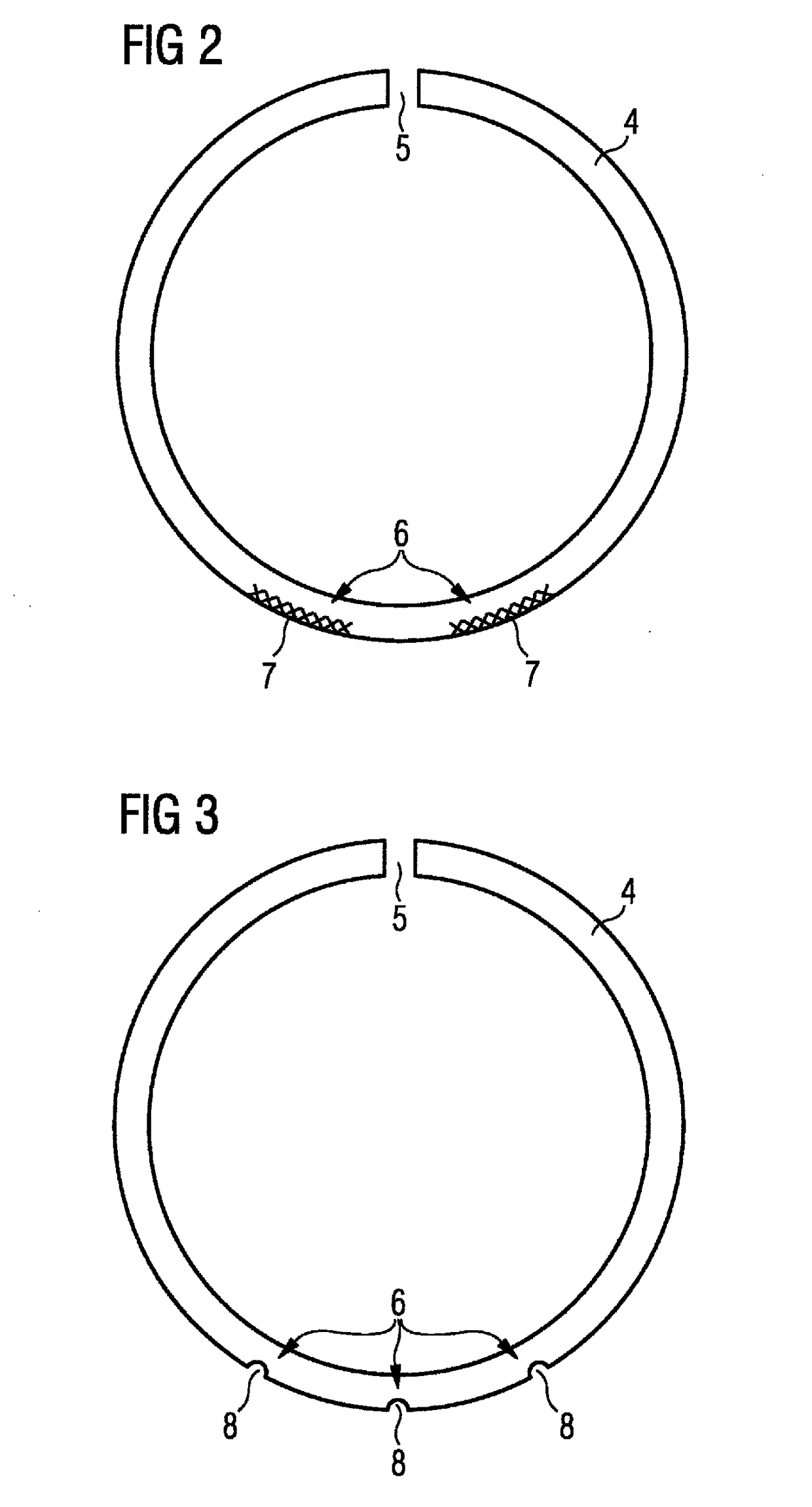
[0012]A secure connection between the support hub and the disk without preventing the expansion of the support hub in the process is achieved with a notch when the notch is arranged in a region whose ends are arranged at least 90° away from the slot. Accordingly, no notch is arranged in each case at least 90° to the left and to the right of the slot. In this region, a relative movement between the disk and the support hub can occur during expansion. Stresses are thus minimized.
[0014]In another configuration, the notch can be produced in a particularly simple manner when it is a single cutout in the support hub, which is arranged opposite the slot. A single cutout is often sufficient owing to the low torque to be transmitted. In addition, advantageously such wide regions of the support hub are provided that a relative movement between the plastic and the support hub is permitted.

Problems solved by technology

The disadvantage with this configuration is that, owing to manufacturing tolerances of the shaft, considerable stresses sometimes occur in the support huh when the support hub is pressed on, and these stresses reduce the life of the magnet wheel.
In particularly severe cases, there is the risk of the magnet wheel being impaired, which may result in malfunctions in the position sensor.

Method used


Image

  • Magnet wheel
  • Magnet wheel
  • Magnet wheel

Examples


Embodiment Construction

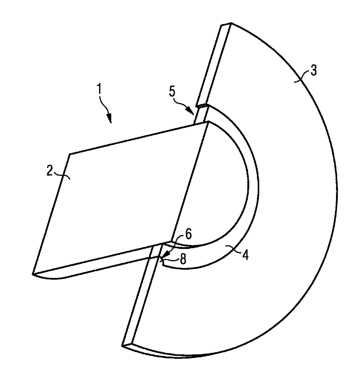
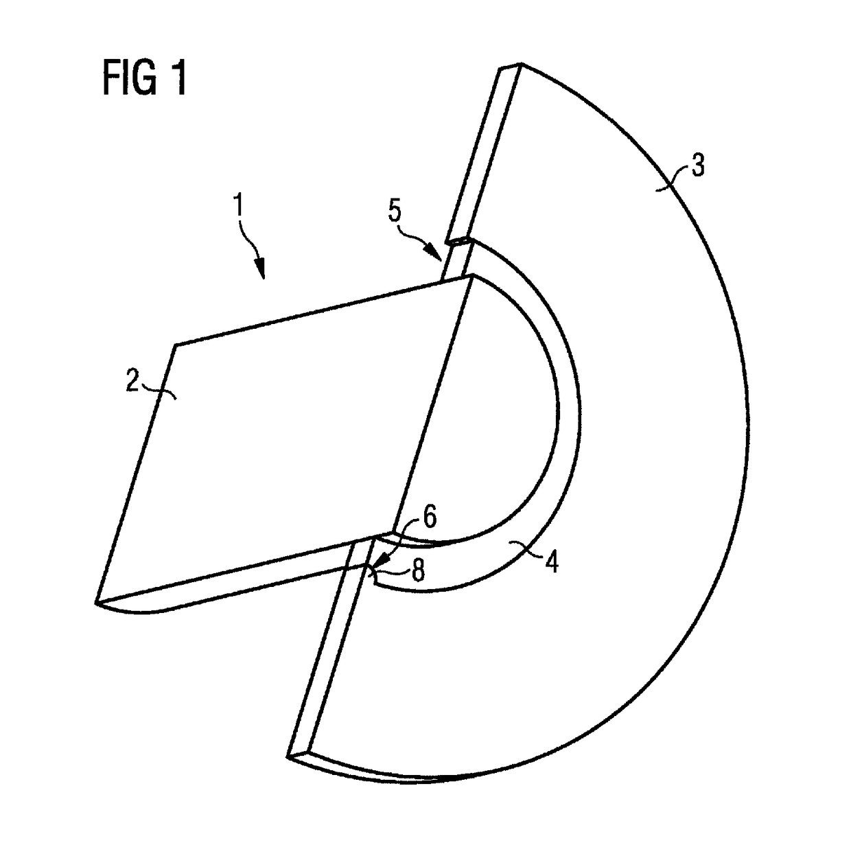
[0019]As seen in FIG. 1, a magnet wheel 1 comprises a shaft 2, which can be the shaft of an electronically commutated electric motor, and a disk 3 made of ferrite-bonded plastic. The plastic is integrally formed on a support hub 4 by injection molding. The support hub has a slot 5, which is arranged in the section plane for improved clarity. As illustrated in FIGS. 1 and 3, the support hub 4 has a notch 6 that may be in the form of a cutout 8 radially on the outside opposite the slot 5 and thus at a distance of 180°. During injection-molding of the ferrite-bonded plastic, the ferrite-bonded plastic fills the notch 6 and thus produces an intimate compound structure with the support hub 4. When the support hub 4 is pressed with the disk 3 onto the shaft 2, the support hub 4 can expand, wherein this may result in relative movements between the support hub 4 and the disk 3 in the regions to the right and left of the slot 5.

[0020]The support hub 4 is illustrated without the disk and the ...


PUM


Abstract

A magnet wheel for an electric motor includes a shaft and a disk made of a plastic containing magnetic particles. The disk is arranged on a carrying hub and the carrying hub is pressed onto the shaft. The carrying hub is a slotted ring around which the disk is molded on by injection molding.

Description

CROSS-REFERENCE TO RELATED APPLICATIONS[0001]This is a U.S. national stage of application No. PCT / EP2012 / 076069, filed on 19 Dec. 2012, which claims priority to the German Application No. 10 2011 089 243.5, filed 20 Dec. 2011, the content of both incorporated herein by reference.BACKGROUND OF THE INVENTION[0002]1. Field of the Invention[0003]The present invention relates to a magnet wheel for an electric motor, having a shaft and a disk made of a plastic containing magnetic particles. The disk is arranged on a support hub, and the support hub is pressed with the shaft.[0004]2. Related Art[0005]Such magnet wheels are used in brushless DC motors as part of position sensors and are therefore known. The disk of the magnet wheel is produced by injection molding a plastic containing iron particles onto the support hub. The support hub is a closed ring made of a suitable material, such as steel or brass. Then, the support hub, with the disk injection-molded on, is pressed onto the shaft. T...

Claims


Application Information

Patent Timeline
Patent Type & Authority Patents(United States)
IPC IPC(8): H02K11/00H02K29/08H02K11/21H02K1/27H02K1/30
CPCH02K1/2733H02K11/21H02K29/08H02K1/30
Inventor SCHRODER, LOTHARWEIMAR, JAN
Owner VITESCO TECH GERMANY GMBH
Learn More