
Driver circuit with frequency-dependent signal feedback

a technology of frequency-dependent signal feedback and driver circuit, which is applied in the direction of pulse generator, pulse technique, oscillation generator, etc., can solve the problems of high cost, large technical investment, and inability to produce components which have to meet very high accuracy requirements, and achieve high longitudinal conversion loss lcl and large manufacturing tolerances

Active Publication Date: 2006-02-28
MAXLINEAR INC
View PDF7 Cites 0 Cited by
  • Summary
  • Abstract
  • Description
  • Claims
  • Application Information

AI Technical Summary

Benefits of technology

[0011]Therefore, the object of the present invention is to provide a driver circuit which, with the use of components with relatively large manufacturing tolerances, nevertheless ensures a very high longitudinal conversion loss LCL.

Problems solved by technology

Such components which have to satisfy very high accuracy requirements can only be produced with considerable technical outlay and high costs.

Method used


Image

  • Driver circuit with frequency-dependent signal feedback
  • Driver circuit with frequency-dependent signal feedback
  • Driver circuit with frequency-dependent signal feedback

Examples


Embodiment Construction

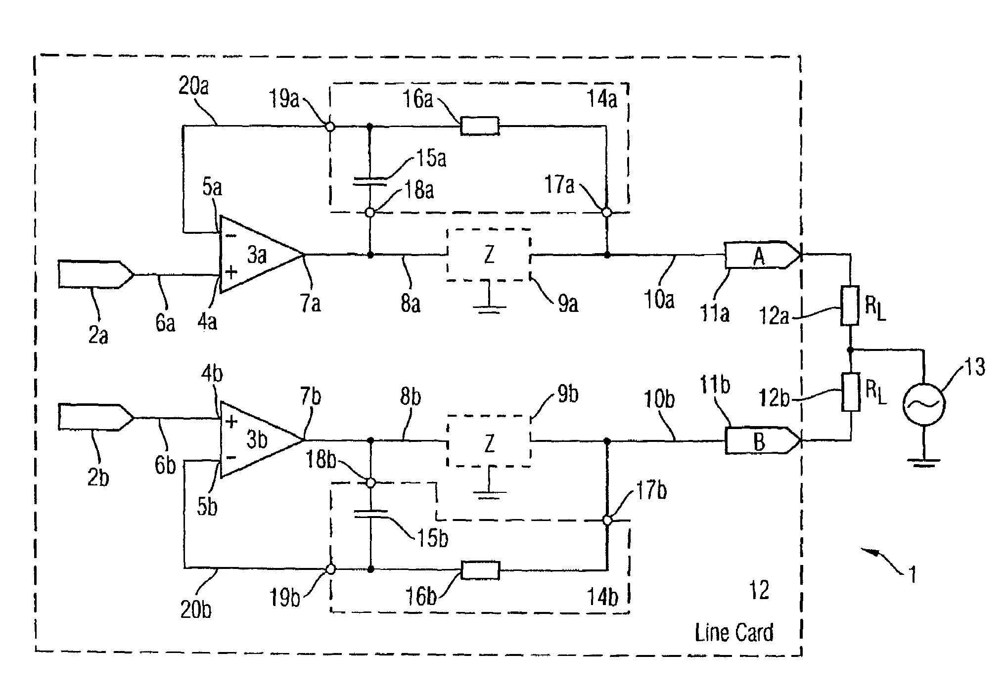
[0031]A preferred embodiment of the driver circuit according to the invention for driving a useful signal is explained in detail below with reference to FIG. 5. The driver circuit 1 as illustrated in FIG. 5 serves for driving a useful signal, for example a voice signal for the transmission of an analog voice signal to a telephone terminal.

[0032]FIG. 5 shows a measuring circuit for measuring the longitudinal conversion loss LCL in the driver circuit 1 according to the invention. The driver circuit 1 illustrated in FIG. 5, which is of differential construction, contains two signal inputs 2a, 2b for receiving a useful signal to be driven. The driver circuit 1 furthermore contains two amplifier circuits 3a, 3b in the form of operational amplifiers each having a noninverting input 4a, 4b and an inverting signal input 5a, 5b. The noninverting signal input 4a, 4b is connected to the associated signal input 2a, 2b via a signal line 6a, 6b. The operational amplifier 3a, 3b respectively has a...


PUM


Abstract

Driver circuit for driving a useful signal having: (a) at least one amplifier circuit (3a, 3b) with low output impedance for the signal amplification of the useful signal; (b) a protection impedance (9a, 9b) respectively connected downstream of the amplifier circuit (3a, 3b) and serving to protect the amplifier circuit (3a, 3b); characterized in that (c) provision is respectively made of a feedback circuit (14a, 14b) for the frequency-dependent signal feedback of the useful signal amplified by the amplifier circuit (3a, 3b).

Description

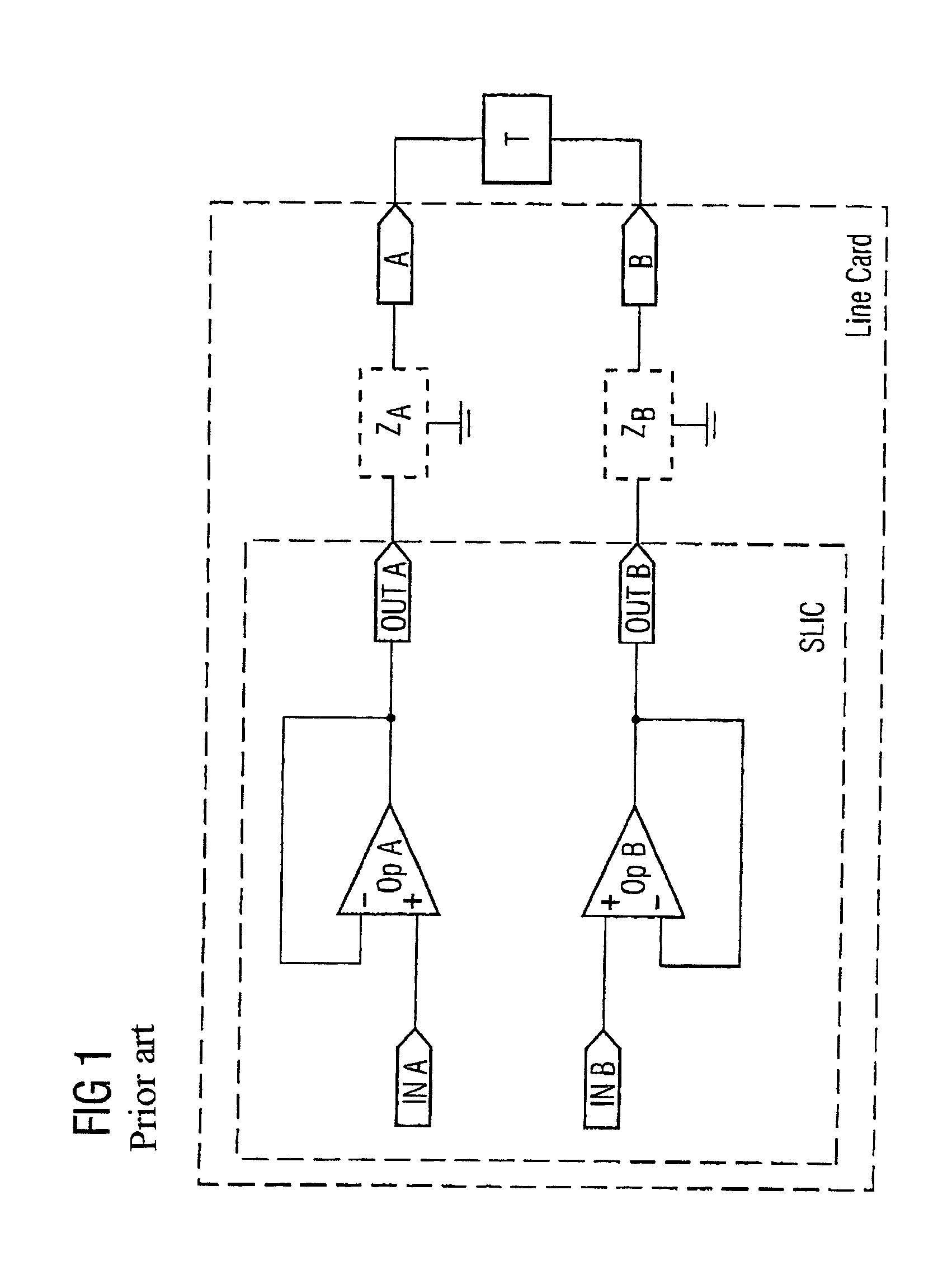
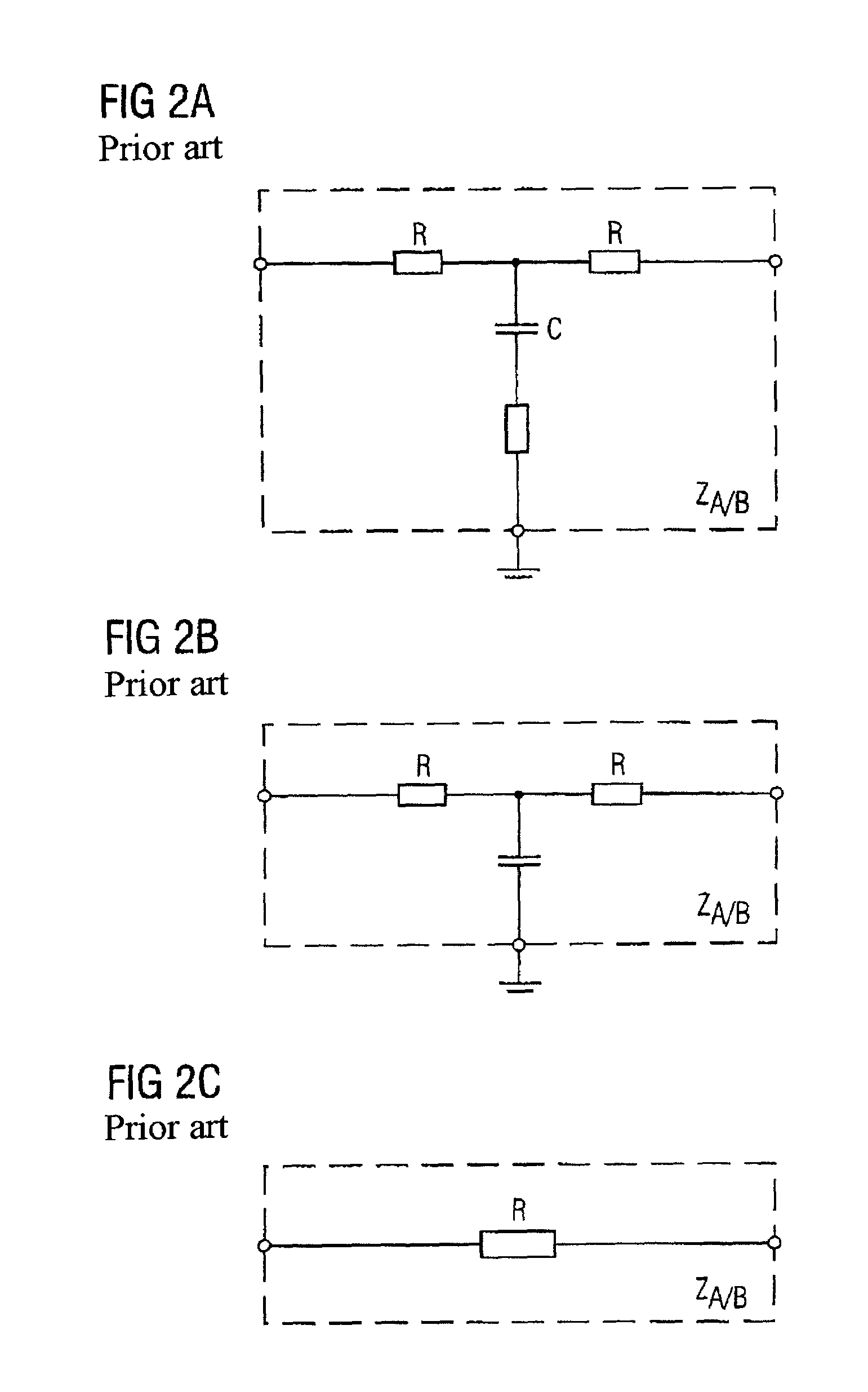
TECHNICAL FIELD[0001]The invention relates to a driver circuit for driving a useful signal in accordance with the preamble of Patent claim 1.BACKGROUND ART[0002]FIG. 1 shows a driver circuit according to the prior art for driving a useful signal.[0003]The driver circuit illustrated in FIG. 1 is of differential construction and contains two operational amplifiers OPA, OPB for signal amplification. The operational amplifiers amplify a useful signal arriving from a signal source and output the amplified useful signal via protection impedances Za, Zb to a connected terminal, for example a telephone T. The operational amplifiers are integrated for example in an SLIC circuit situated on a line card. The operational amplifiers each have a low output impedance for the signal amplification of the useful signal. The impedances connected downstream of the two operational amplifiers serve to protect the amplifier circuits and for electromagnetic compatibility (EMC). The output impedances Za, Zb...

Claims


Application Information

Patent Timeline
Patent Type & Authority Patents(United States)
IPC IPC(8): H03B1/00H03F1/34H03F1/52H03F3/45
CPCH03F1/34H03F3/45475H03F1/52
Inventor FERIANZ, THOMAS
Owner MAXLINEAR INC
Learn More