
Camshaft Adjuster for an Internal Combustion Engine

a technology for internal combustion engines and camshafts, which is applied in the direction of yielding couplings, valve arrangements, couplings, etc., can solve the problems of only being able to achieve tolerances and still not in the desired position of camshafts relative to crankshafts, so as to achieve greater tolerances, reduce the mass of moving parts, and increase the turning angle

Inactive Publication Date: 2007-07-26
SKN SINTER METALS LLC (US)
View PDF1 Cites 0 Cited by
  • Summary
  • Abstract
  • Description
  • Claims
  • Application Information

AI Technical Summary

Benefits of technology

[0014] The invention provides a camshaft adjuster for internal combustion engines which prevents internal radial leaks and can be produced economically.
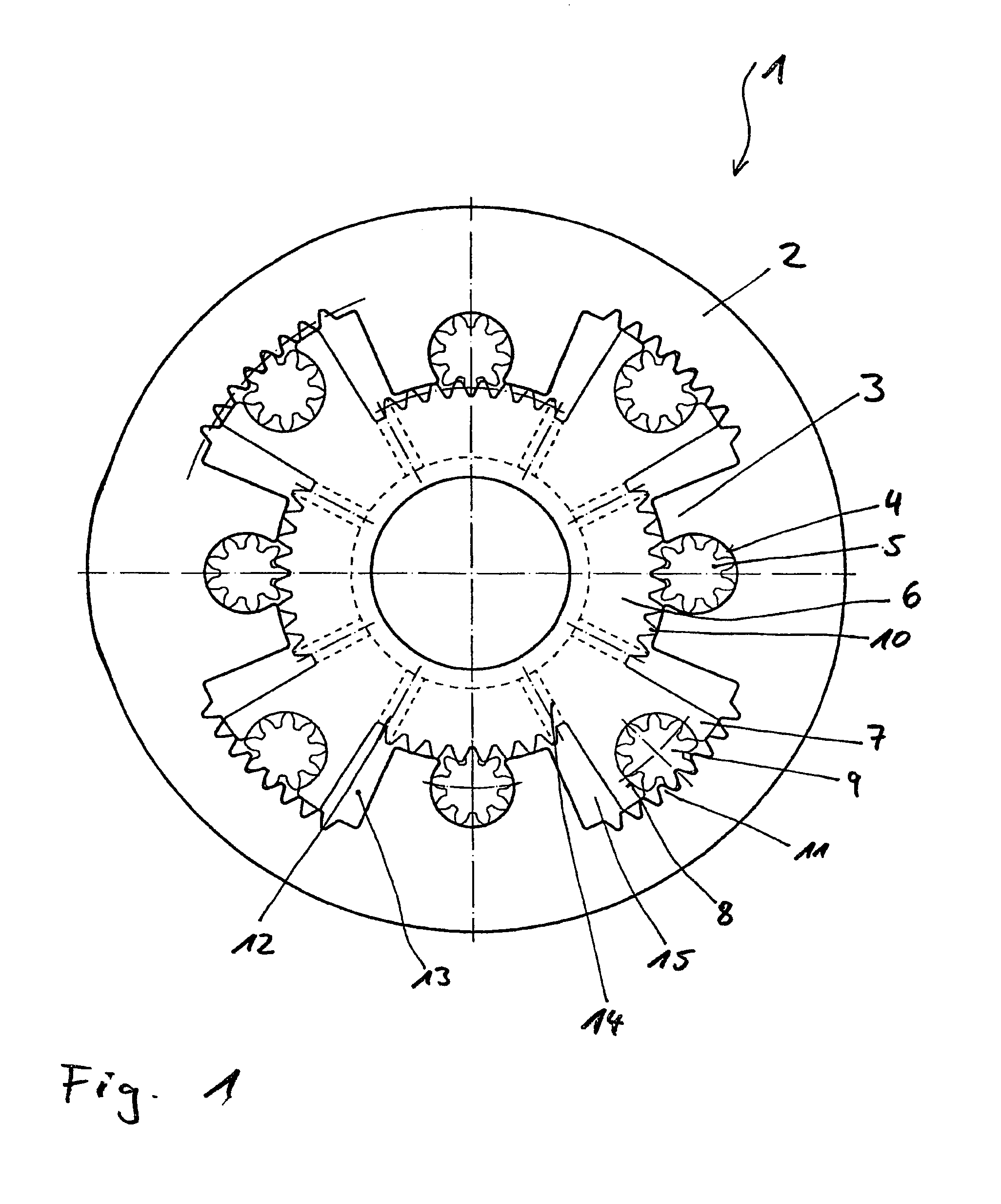
[0016] Internal radial leakages, which arise between the contact points of the stator and the inner rotor in the form of gap losses, must be prevented by the introduction of a sealing element between the inner rotor and the stator, or by narrowed tolerances. The gap losses are prevented by the introduction of a denticulated segment in the form of an outer denticulation between two rotor vanes on the inner rotor and a planet gear mounted in the stator vane, where said planet gear meshes with the denticulated segment of the inner rotor. In addition, a denticulated segment, in the form of an inner denticulation between the stator vanes, is provided on the stator, where, in the rotor vane, a rotor vane planet gear is mounted which meshes with the denticulated segment of the stator.
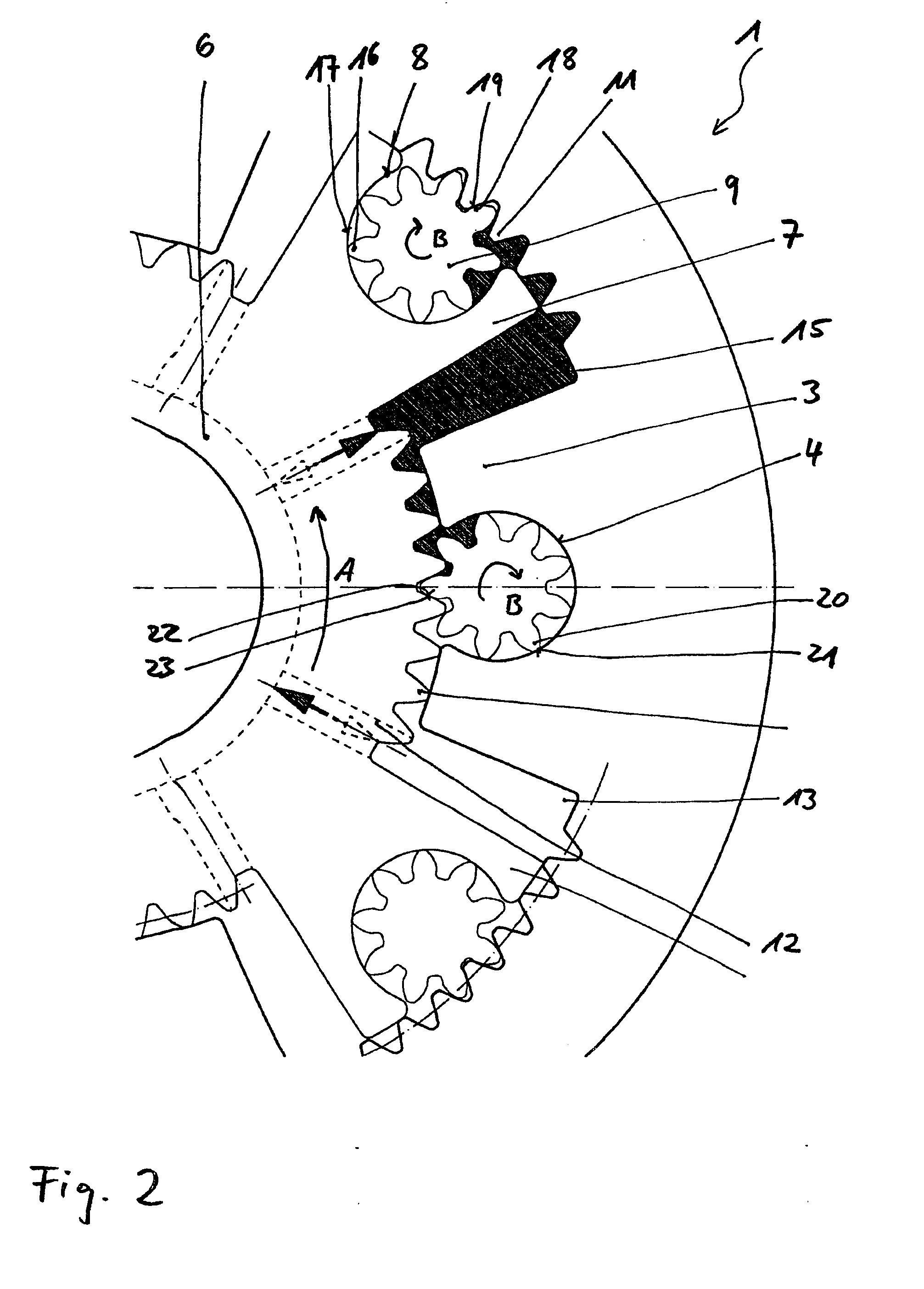
[0018] In order to avoid faults in engagement, the geometry of the denticulation must be designed so that the denticulation data of the planet gears which are mounted in the rotor vane and in the stator vane are equal. In this way, the production costs are also lowered since in sintering-based production of the rotor vane planet gears and stator planet gears only one tool is used. The adjustment of the inner rotor is done by pressure being increased in a pressure chamber, where depending on the pressurized pressure chamber the pressure is against the inner rotor vane and turns it accordingly. Due to the oil pressure in the pressure chamber, the stator vane planet gear which meshes with the denticulated segment of the inner rotor is pressurized, where due to this pressurization the tooth points of the stator vane planet gear are pressed against the wall of the mounting pocket in the stator vane and the tooth flanks of the stator vane planet gear are pressed against the tooth flanks of the denticulated segment of the inner rotor.
[0020] In an advantageous development of the invention it is provided that the stator comprises at least two stator vanes and the rotor comprises at least two rotor vanes. In a further advantageous development it is provided that the stator comprises three stator vanes and the rotor comprises three rotor vanes. In an also advantageous development of the invention it is provided that the stator comprises four stator vanes and the rotor comprises four rotor vanes. Known camshaft adjusters customarily comprise four stator vanes and four rotor vanes, due to which the possible turning angles of the camshaft are limited by considerations of construction. A reduction of the number of stator vanes and rotor vanes to two or three vanes leads to the result that, on the one hand, larger turning angles can be realized and, on the other hand, the camshaft adjuster becomes lighter and there is a lower mass for moving parts. From the standpoint of construction more than four vanes are also possible.
[0021] In a particularly advantageous development of the invention it is provided that the stator, the inner rotor, and / or the planet gears consist of sintered metal. Using sintering technology, these parts can be manufactured with greater tolerances without the radial sealing being impaired. Furthermore, the sensitivity to contaminated oil is low.
[0022] An additional advantage of the relatively large manufacturing tolerances is the possibility of using materials other than sintered aluminum or plastic. It is advantageous if the rotor, the stator, and the planet gears have approximately equal coefficients of thermal expansion so that these components can be paired with one another. With approximately equal coefficients of thermal expansion it is possible, for example, to use a rotor and stator of sintered steel and the planet gears of plastic (Duroplast). In this way, in particular, a reduction of the noise results with the pairing of sintered steel / plastic.

Problems solved by technology

In so doing, there is the problem that, precisely in the motor start phase critical for exhaust gas, the camshaft is still not in the desired position relative to the crankshaft.
It is problematic in camshaft adjusters of this type that, to avoid greater internal leakage in the pressure chambers, narrow tolerances must be adhered to, which can only be adhered to with undesirable expenditure, in particular if components of this type are produced with sintering technology.
In production using sintering technology these tolerances can thus only be achieved by corresponding complicated mechanical processing, or via clearly reduced number of pieces.

Method used


Image

  • Camshaft Adjuster for an Internal Combustion Engine
  • Camshaft Adjuster for an Internal Combustion Engine
  • Camshaft Adjuster for an Internal Combustion Engine

Examples


Embodiment Construction

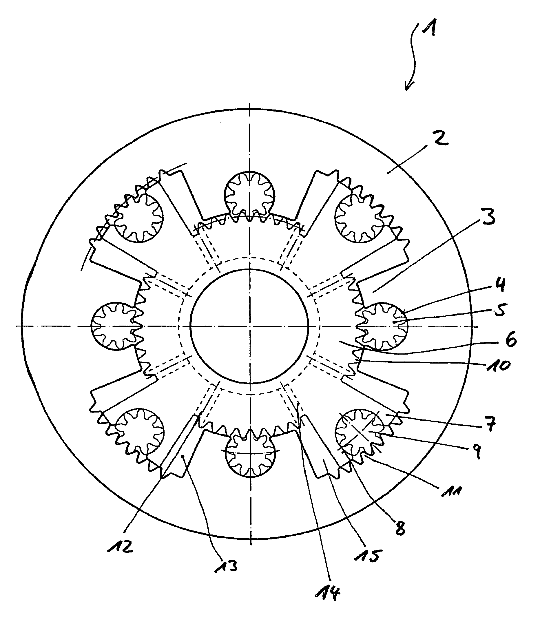
[0027]FIG. 1 shows a camshaft adjuster 1 for an unrepresented internal combustion engine with a stator 2 which comprises, distributed over its periphery, stator vanes 3 projecting inwards in the radial direction. Each of the stator vanes 3 comprises a mounting pocket 4 which is open in the inward direction and in which a stator vane planet gear 5 is mounted. Mounted in the stator 2 is a rotor 6 which comprises rotor vanes 7. Each rotor vane 7 comprises a mounting pocket 8 which is open in the outwards direction and in which a rotor vane planet gear 9 is mounted.

[0028] Each of the stator vanes 3 projects inwards in the radial direction into the spaces between the two rotor vanes 7. The same holds for the rotor vanes 7, each of which projects cleanly into the intervening space. Thus it follows that the rotor 6 is formed to have approximately the form of a star.

[0029] The stator vane planet gear 5 disposed in the stator vane 3 meshes with a denticulated segment 10 disposed on the out...


PUM


Abstract

A camshaft adjuster for an internal combustion engine comprises a stator having inwardly projecting stator vanes, which are distributed over the periphery of the stator and which have at least one stator vane accommodating pocket located in the stator. This stator vane accommodating pocket is open toward the interior and a stator vane planet gear is mounted inside the stator vane accommodating pocket. A rotor is mounted inside the stator and comprises rotor vanes having at least one rotor vane accommodating pocket open toward the exterior, inside of which a rotor vane planet gear is mounted. The stator vane planet gears mesh with a denticulated segment located on the outer periphery of the rotor between each of the rotor vanes, and the rotor vane planet gears mesh with a denticulated segment located on the inner periphery of the stator between each of the stator vanes.

Description

FIELD OF THE INVENTION [0001] The invention relates to a camshaft adjuster for internal combustion engines. BACKGROUND OF THE INVENTION [0002] Camshaft adjusters of the aforementioned type serve to make possible valve control which is variable or as optimized as possible. They offer the possibility of adjusting the phase angle of the valve control continuously and in a controlled manner. For this, a camshaft adjuster is connected to the respective camshaft in a manner that it is fixed against turning and force-locking. [0003] Depending on the presetting of monitoring and control electronics, a turning motion is transmitted to the camshaft and thereby a respective desired setting of the camshaft relative to the crankshaft of the internal combustion engine is preset. [0004] Customary camshaft adjusters are usually driven hydraulically. The oil pressure needed to adjust the camshaft is obtained from the lubricant oil circuit associated with the internal combustion engine in question. I...

Claims


Application Information

Patent Timeline
Patent Type & Authority Applications(United States)
IPC IPC(8): F01L1/34F01L1/344F01L1/352
CPCF01L1/3442F01L2820/01F01L2001/34479F01L1/352F01L1/344
Inventor BACHMANN, JOSEFSCHWARZE, ROLF
Owner SKN SINTER METALS LLC (US)
Learn More