Equilibration of a multibeam inductive output tube

a multi-beam inductive output tube and output tube technology, which is applied in the direction of transit-tube cathodes, transit-tube circuit elements, amplifiers with tubes, etc., can solve the problems of increasing the manufacturing cost of tubes, and achieve the effects of reducing manufacturing tolerances, and reducing the manufacturing cost of tubes

Active Publication Date: 2019-11-26
THALES SA
View PDF9 Cites 0 Cited by
  • Summary
  • Abstract
  • Description
  • Claims
  • Application Information

AI Technical Summary

Benefits of technology

[0006]One solution consists in decreasing manufacturing tolerances, but this tends to increase the manufacturing cost of a tube.
[0007]The invention aims to mitigate this problem while accepting larger manufacturing tolerances. The invention provides a solution allowing the density of the various beams to be balanced independently of geometric dispersions.

Problems solved by technology

One solution consists in decreasing manufacturing tolerances, but this tends to increase the manufacturing cost of a tube.

Method used


Image

  • Equilibration of a multibeam inductive output tube
  • Equilibration of a multibeam inductive output tube

Examples


Embodiment Construction

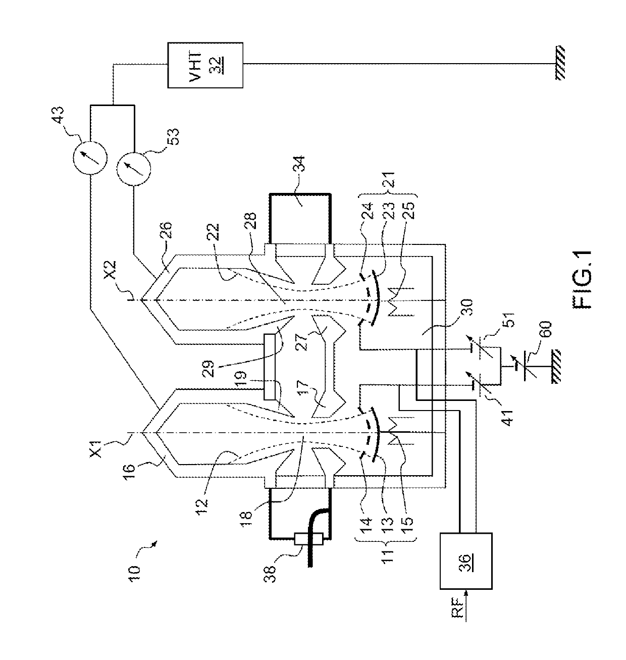
[0019]FIG. 1 shows an amplifier 10 intended to amplify a radiofrequency signal by means of a vacuum tube. It will be recalled, briefly, that a vacuum tube uses the principle of interaction between an electron beam and an electromagnetic wave to transmit, to the wave, some of the energy contained in the electron beam, so as to obtain, as output from the tube, a wave of higher energy than the wave input into the tube. The frequency of the radiofrequency signal is for example in the UHF band. Other frequency bands may of course be employed in the context of the invention.

[0020]The amplifier 10 comprises, by way of example, two electron guns 11 and 21 that each emit a beam, 12 and 22, respectively, in a vacuum chamber 30. The number of guns has been chosen in order not to overload the figure. It is of course possible to implement the invention with a larger number of guns. The applicant has for example carried out conclusive internal trials with an amplifier possessing ten electron guns...


PUM


Abstract

A multibeam-inductive-output-tube amplifier comprises an output cavity and a plurality of electron guns each intended to emit an electron beam through the output cavity, each electron gun comprising a cathode intended to emit the electron beam and a gate allowing the density of the electron beam to be modulated. The amplifier comprises, associated with each gun, a DC voltage supply, each of the supplies connected to the gate of the corresponding electron gun so as to bias the gate. The voltage of at least one of the supplies is adjustable so as to balance the density of the various electron beams.

Description

CROSS-REFERENCE TO RELATED APPLICATIONS[0001]This application is a National Stage of International patent application PCT / EP2016 / 073548, filed on Oct. 3, 2016, which claims priority to foreign French patent application No. FR 1502085, filed on Oct. 7, 2015, the disclosures of which are incorporated by reference in their entirety.FIELD OF THE INVENTION[0002]The invention relates to an inductive-output-tube amplifier. Such tubes are well known in the literature as IOTs. The tube includes, in a vacuum chamber, a gun that generates an electron beam that passes through an anode and an interaction space before reaching a collector. The interaction space is located in a resonant cavity. An input signal input level with the electron gun is amplified level with the resonant cavity. Inductive output tubes are in particular used in the last amplification stage of radiofrequency signals, the output of the tube being connected to a load such as for example an accelerating cavity.BACKGROUND[0003]...

Claims


Application Information

Patent Timeline
Patent Type & Authority Patents(United States)
IPC IPC(8): H03F1/00H01J23/04H01J23/027H01J25/04H03F3/02H01J23/06H01J23/16
CPCH03F3/02H01J23/16H01J23/04H01J23/027H01J25/04H01J23/06
Inventor BEL, CLAUDE
Owner THALES SA
Why Eureka
Try Eureka