Permanent magnet rotor

a permanent magnet rotor and permanent magnet technology, applied in the direction of motors, wind energy generation, dynamo-electric machines, etc., can solve the problems of high cost of materials, cumbersome manufacturing process, and inability to meet the needs of continuous axial cross-section, and achieve the effect of reducing the loss of magnetic flux, facilitating assembly and maintenance, and constant axial cross-section

Active Publication Date: 2015-07-09
GE RENEWABLE TECH WIND BV
View PDF10 Cites 4 Cited by
  • Summary
  • Abstract
  • Description
  • Claims
  • Application Information

AI Technical Summary

Benefits of technology

[0011]In this aspect of the invention, the arrangement of the magnets inclined with respect to the local radial plane lead to beneficial power and torque characteristics. Additionally, loss of magnetic flux is minimized by the magnetic saturation of the outer bridges between the principal magnets and the outer circumference of the rotor provided by the magnetic field generated by the auxiliary magnets. The magnetic flux of the permanent magnets is thus all directed from the rotor to the stator.
[0014]In some embodiments, the auxiliary magnets may be made from a different material than the principal magnets. The material of the auxiliary magnets may be cheaper than the material used for the permanent magnets.
[0015]In some embodiments, inner bridges of magnetic material may be formed between the inner ends of the principal magnets and portions of non-magnetic material, and wherein auxiliary magnets are arranged near the inner ends of the principal magnets to magnetically saturate the inner bridges. In these embodiments, the loss of magnetic flux may be further reduced.
[0016]In some embodiments, the rotor body may comprise a rim and a plurality of permanent magnet modules arranged on the outer or inner circumference of the rim, wherein each of the permanent magnet modules extends generally along an axial direction and being of substantially constant axial-cross-section, and has a base adapted to be fixed to the rim, and one or more axial rows of permanent magnets and rows of auxiliary magnets, and one or more pole pieces. In these embodiments using modules, assembly and maintenance is facilitated. Both for repair and manufacture, modules of magnets can be relatively easily inserted in place and removed. In alternative embodiments, the permanent magnets may be embedded in a more solid rotor core that extends from a shaft to an outer circumference (in case the stator surrounds the rotor).
[0018]In some embodiments, the base and pole pieces of the permanent magnet modules may be integrally formed and the magnets may be embedded in the permanent magnet modules. If the base and pole pieces are integrally formed (i.e. they form a monolithic piece) in axial cross-section, the manufacturing tolerances for the modules may be reduced.
[0020]In these embodiments, a particularly easy way of installing the modules on the rotor rim is provided. The anchors may first be loosely attached to the rotor rim. After placement of the module, the anchor may be tightened and may engage with the base of the module.

Problems solved by technology

It will be clear that this manufacturing process can be cumbersome.
Furthermore, if one or more magnets is damaged and needs to be replaced, the access to these magnets can be complicated (especially with large size generators), such that maintenance can become very expensive.
These materials may be relatively expensive.
Incorporation of a cooling circuit may further complicate the assembly and manufacture of large permanent magnet generators.
These radial holes may complicate manufacture and assembly and will generally not lead to homogeneous cooling.
Also relatively large permanent magnet motors may have the same or similar problems.

Method used


Image

  • Permanent magnet rotor
  • Permanent magnet rotor
  • Permanent magnet rotor

Examples


Embodiment Construction

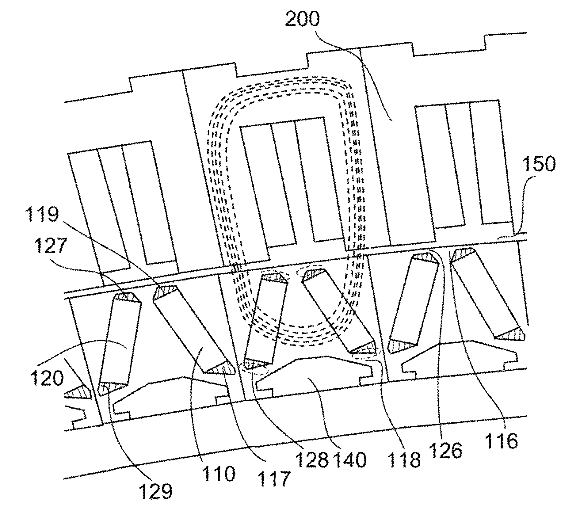
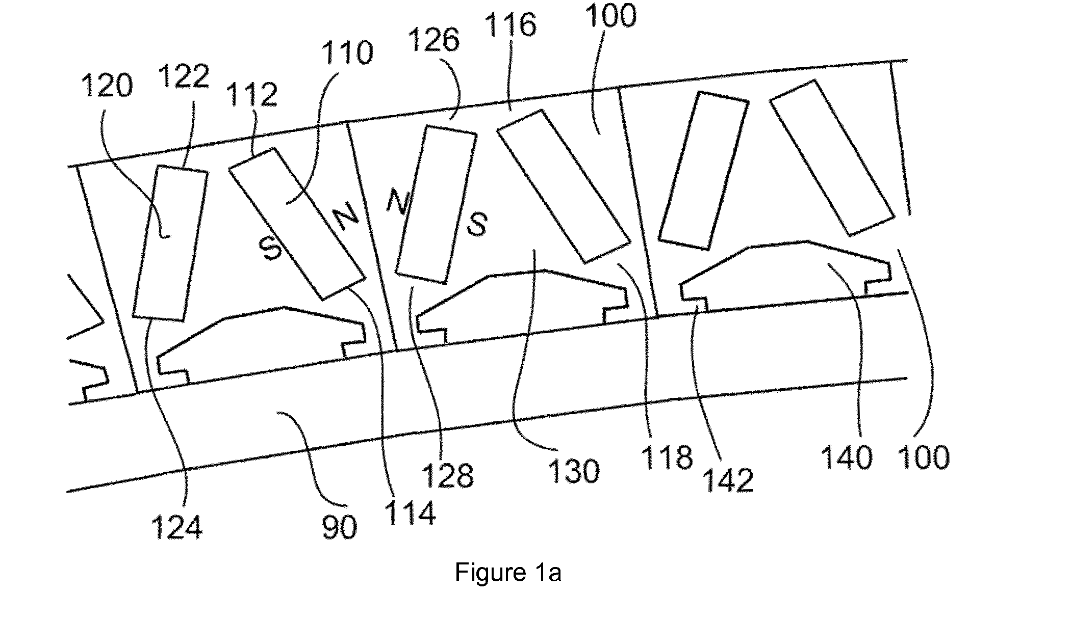
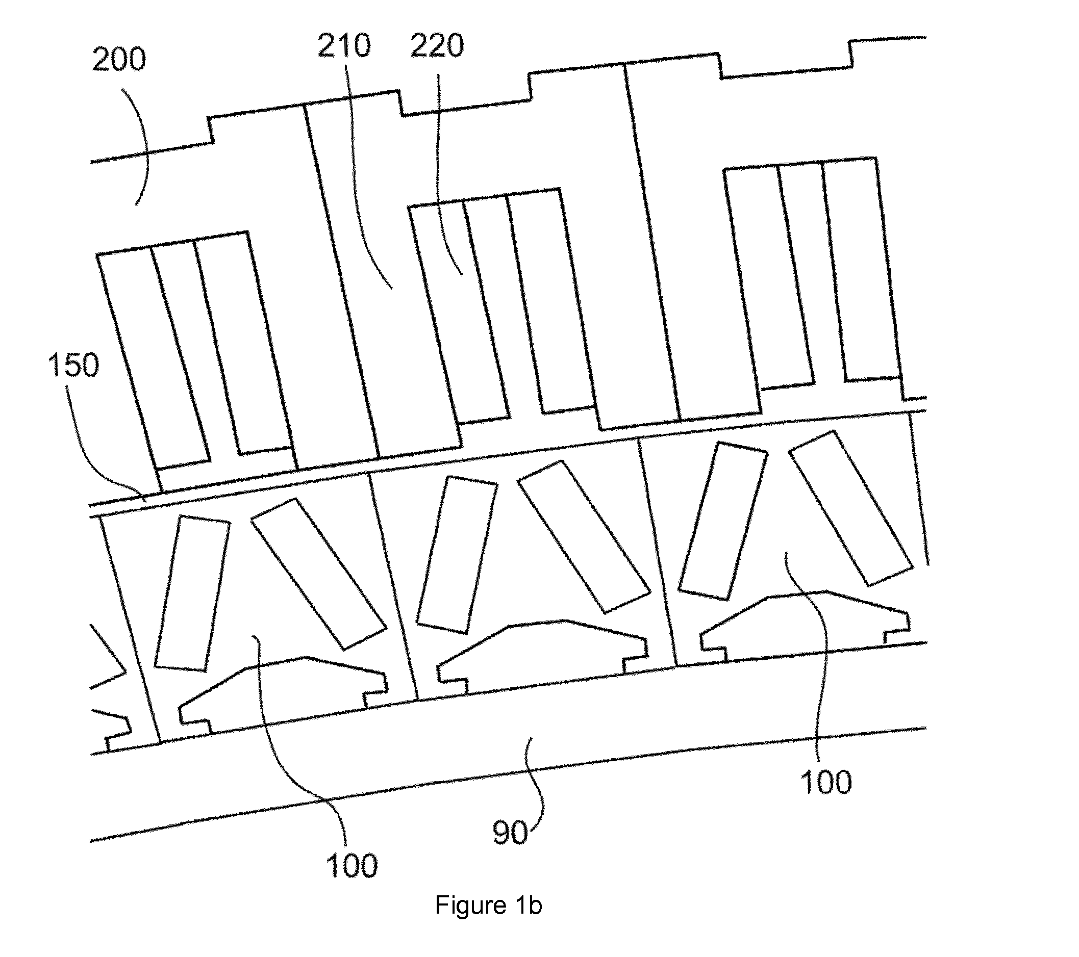
[0030]FIG. 1a schematically illustrates an outer edge region of a permanent magnet rotor of an electrical machine, e.g. a generator of a wind turbine. The rotor in this example may comprise a rim 90 and a plurality of modules 100 attached to the radially outer circumference of the rim 90. The use of modules may facilitate assembly and repair, particularly of large generators, such as generators that may be found on direct drive wind turbines.

[0031]Each module 100 may comprise a first and second principal permanent magnet 110 and 120 respectively arranged on a base 130. The base 130 has an upper portion with a substantially isosceles triangular cross-section with the permanent magnets arranged along the sides of the triangle.

[0032]The permanent magnets 110 and 120 are arranged to be inclined with respect to a local radial plane. The magnets have a circumferential magnetic orientation (also sometimes referred to as “transversal” or “tangential” orientation), i.e. the North and South o...


PUM


Abstract

A permanent magnet rotor comprises a rotor body configured for rotating around a central rotational axis and further comprises principal permanent magnets that are substantially rectangular in axial cross-section and are embedded in the rotor body and are arranged inclined with respect to the radial plane extending through the centre of the principal magnets and such as to have a circumferential magnetic orientation. The principal magnets have an inner end and an outer end, the outer end being arranged in the proximity of the air gap of the outer circumference of the rotor, and outer bridges of magnetically conductive material being formed between the outer ends of the principal magnets and the outer circumference of the rotor. Auxiliary magnets are arranged near the outer ends of the principal magnets to magnetically saturate the outer bridges.

Description

[0001]This application claims the benefit of European Patent Application 12 382 260.3 filed 29 Jun. 2012 and U.S. Provisional Patent Application Ser. No 61 / 694,575 filed 29 Aug. 2012.[0002]The present disclosure relates to a permanent magnet rotor for an electrical machine. The present disclosure also relates to a permanent magnet generator rotor especially suitable for a wind turbine, and to a wind turbine comprising such a permanent magnet generator rotor.BACKGROUND ART[0003]Electrical machines, such as motors and generators having a rotor with permanent magnets are known. They are generally deemed to be reliable and require less maintenance than other generator topologies.[0004]Modern wind turbines are commonly used to supply electricity into the electrical grid. Wind turbines of this kind generally comprise a rotor with a rotor hub and a plurality of blades. The rotor is set into rotation under the influence of the wind on the blades. The rotation of the rotor shaft either direc...

Claims


Application Information

Patent Timeline
Patent Type & Authority Applications(United States)
IPC IPC(8): H02K1/27H02K1/28F03D9/00H02K1/32
CPCH02K1/2766F03D9/002H02K1/28H02K1/32H02K7/1838H02K2213/12Y02E10/72F03D9/25
Inventor MUNIZ CASAIS, CESAR
Owner GE RENEWABLE TECH WIND BV
Why Eureka
Try Eureka