
Double rotor type motor

a double rotor type, motor technology, applied in the direction of magnetic circuit rotating parts, other washing machines, magnetic circuit shapes/forms/construction, etc., can solve the problems of increasing the size and weight of the motor, generating a lot of noise in the power transmission course, and energy loss, so as to shorten the time period, facilitate and accurate positioning of the outer rotor, and strengthen the torque

Active Publication Date: 2011-03-22
LG ELECTRONICS INC
View PDF14 Cites 17 Cited by
  • Summary
  • Abstract
  • Description
  • Claims
  • Application Information

AI Technical Summary

Benefits of technology

The present invention provides a double rotor type motor that can increase the output of the motor without increasing the size of the motor significantly. This motor includes an outer rotor and an inner rotor with magnets mounted on their respective extensions, and a bushing for transmitting rotation force from both the outer and inner rotors to a rotating shaft. The motor is designed to increase the output of the motor without increasing the size of the motor significantly.

Problems solved by technology

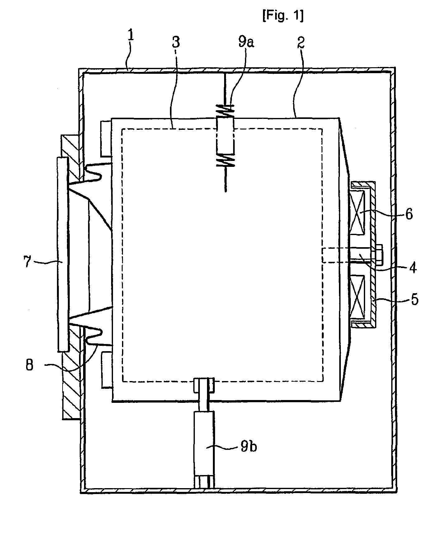
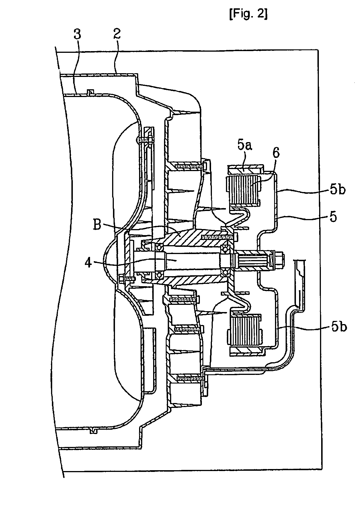
The type of washing machine in which driving power is transmitted from the motor to the drum indirectly through a belt wound around a motor pulley and a drum pulley causes an energy loss in a course of the driving power transmission, and generates much noise in the power transmission course.
However, currently, keeping pace with capacity increase of the washing machine, though it is required to increase an output of the motor for rotating the drum too, such an increased output of the motor requires large sized rotor and stator, to increase size and weight of the motor, significantly.
Consequently, the increase of the motor size causes to increase a size of the washing machine or the like having the motor applied thereto, significantly.

Method used


Image

  • Double rotor type motor
  • Double rotor type motor
  • Double rotor type motor

Examples


Embodiment Construction

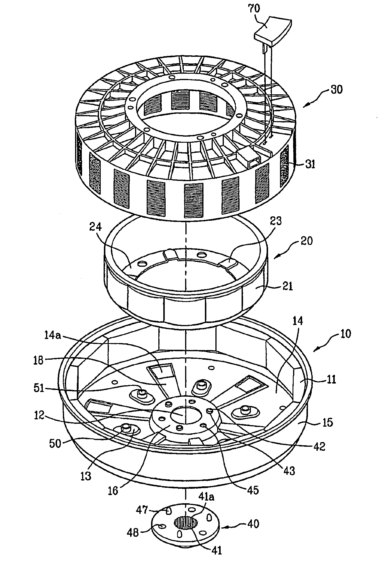
[0067]Double rotor type motors in accordance with a first preferred embodiment of the present invention will be described with reference to FIGS. 3 to 11.

[0068]FIG. 3 illustrates an exploded perspective view a double rotor type motor in accordance with a first preferred embodiment of the present invention, and FIG. 4 illustrates a section of the double rotor type motor and a portion of a motor mounting portion in accordance with a first preferred embodiment of the present invention.

[0069]Referring to FIG. 3, the double rotor type motor includes an inner rotor 20, an outer rotor 10, and a stator 30. Placed between the outer rotor 10 and the inner rotor 20, there is the stator 30, and a top side of the stator 30 is fixedly secured to a bearing housing mounted to a rear of a washing machine tub. On one side of the stator 30, there is a hall sensor 70 for detecting a rotation speed of the double rotor.

[0070]The stator 30 includes cores 31 exposed, and opposite to inner magnets 21 on the...


PUM


Abstract

The present invention relates to motors, and more particularly, to a double rotor type motor applicable to a washing machine or the like. The double rotor type motor includes an outer rotor having first base, and a first extension extended from a circumference of the first base substantially perpendicular thereto, the first extension having outer magnets mounted on an inside circumferential surface, an inner rotor having a second base mounted on an upper surface of the first base concentric to the first base, and a second extension extended from a circumference of the second base so as to be opposite to the first extension with a predetermined gap toward an inner side of the first extension, the second extension having inner magnets mounted on an outside circumferential surface, and a bushing at a center of the first base and the second base, for transmission of rotation force both from the outer rotor and the inner rotor to a rotating shaft.

Description

TECHNICAL FIELD[0001]The present invention relates to motors, and more particularly, to a double rotor type motor applicable to a washing machine or the like.BACKGROUND ART[0002]In general, the washing machine washes laundry by using friction between washing water and the laundry in a drum rotated by a motor in a state detergent, washing water, and the laundry is introduced into the drum. The drum is a washing tub for holding washing water and the laundry, and applicable to the washing machine, irrespective of the washing machine being of a drum type or a pulsator type.[0003]In the meantime, depending on driving types of the washing machine, there are indirect coupling type in which driving power is transmitted from the motor to the drum indirectly through a belt wound around a motor pulley and a drum pulley, and a direct coupling type in which the motor is directly coupled to the drum, to transmit driving power from the motor to the drum, directly.[0004]The type of washing machine ...

Claims


Application Information

Patent Timeline
Patent Type & Authority Patents(United States)
IPC IPC(8): H02K1/22
CPCD06F37/304H02K1/27H02K21/12H02K1/32H02K16/02H02K1/30
Inventor CHOI, SOUNG BONGJEONG, SEONG HAIKIM, YEONG SOOCHO, HUNG MYONGAHN, IN GEUN
Owner LG ELECTRONICS INC
Learn More