Reticle defect inspection apparatus and reticle defect inspection method

a technology of defect inspection and inspection apparatus, applied in the direction of originals for photomechanical treatment, material analysis by optical means, instruments, etc., can solve problems such as light blues in illuminated areas, and achieve the effect of high detection sensibility

Active Publication Date: 2011-03-22
KIOXIA CORP +1
View PDF20 Cites 5 Cited by
  • Summary
  • Abstract
  • Description
  • Claims
  • Application Information

AI Technical Summary

Problems solved by technology

While, if a transmitted illumination area and a reflected illumination area should positionally be separated, settings must be made so that the transmitted illumination area and the reflected illumination area do not overlap, it has become evident that a problem arises in which blurring of illuminated areas occurs due to the focal point shift before being expanded so that the transmitted illumination light penetrates into a reflected imaging area.

Method used


Image

  • Reticle defect inspection apparatus and reticle defect inspection method
  • Reticle defect inspection apparatus and reticle defect inspection method
  • Reticle defect inspection apparatus and reticle defect inspection method

Examples


Embodiment Construction

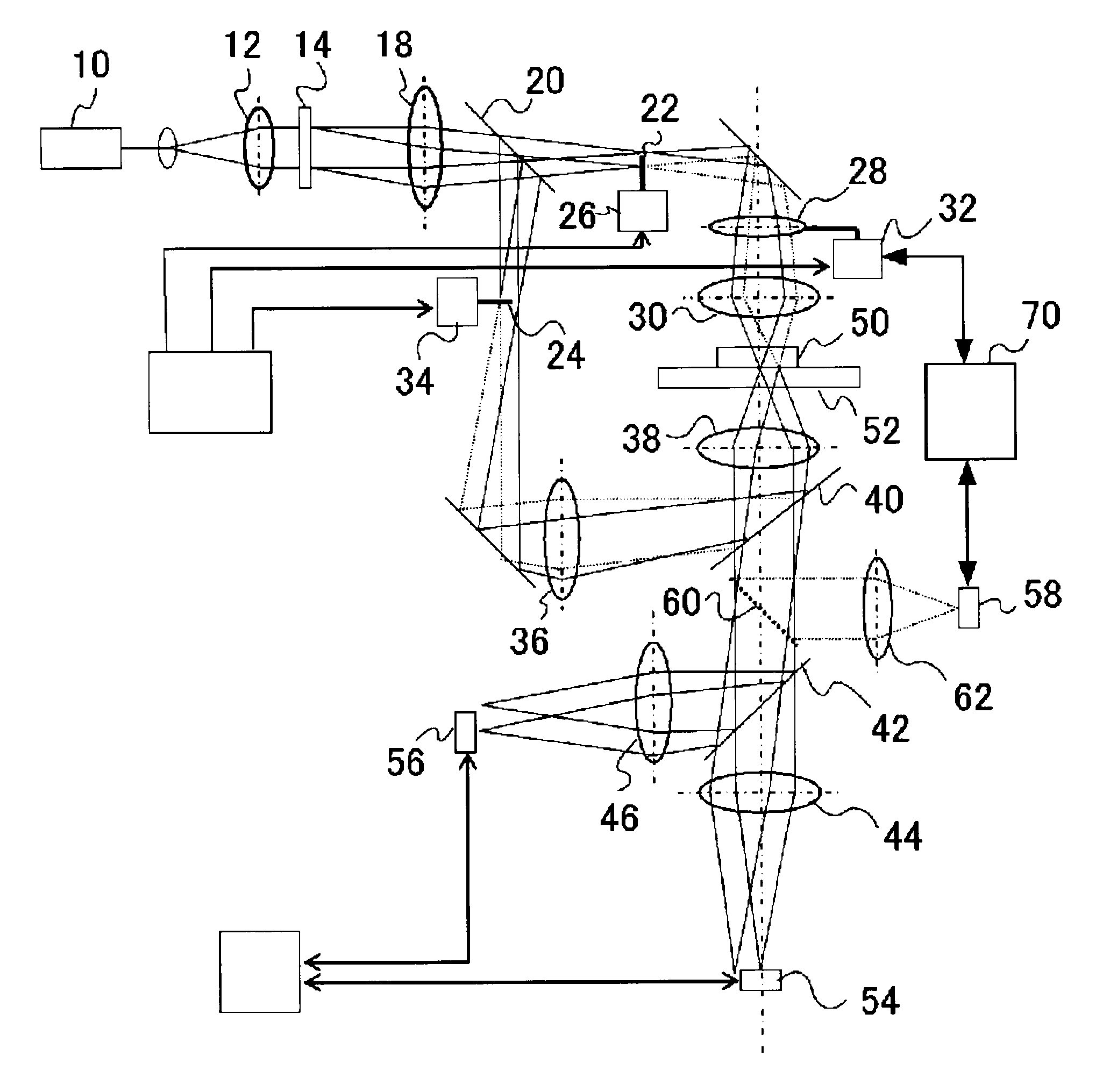
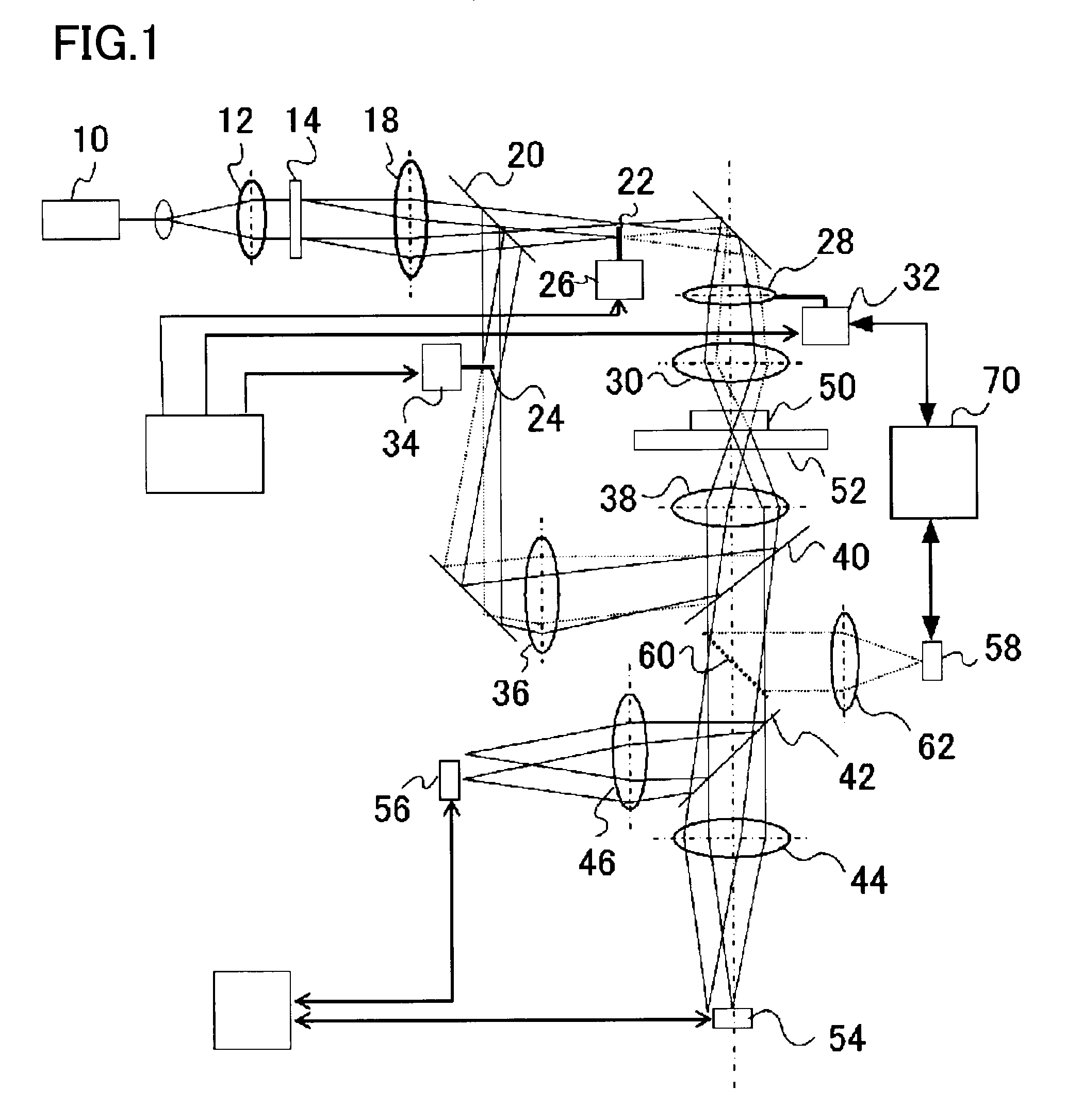
[0024]An embodiment of the present invention will be described below with reference to drawings. A reticle defect inspection apparatus in the present embodiment is a reticle defect inspection apparatus that inspects for defects on a sample by using a pattern image obtained by irradiating the sample on which a pattern is formed with light. The reticle defect inspection apparatus comprises an optical system of transmitted illumination that irradiates one surface of the sample with a first inspection light and an optical system of reflected illumination that irradiates another surface of the sample with a second inspection light. Moreover, the reticle defect inspection apparatus comprises a detecting optical system that can detect a transmitted light by irradiation of the sample with the first inspection light and a reflected light by irradiation of the sample with the second inspection light simultaneously. Further, the optical system of transmitted illumination comprises a lens drivi...


PUM

PropertyMeasurementUnit
sizeaaaaaaaaaa
sizeaaaaaaaaaa
thicknessaaaaaaaaaa

Abstract

A reticle defect inspection apparatus that can carry out a defect inspection with high detection sensitivity are provided. The apparatus includes an optical system of transmitted illumination for irradiating one surface of a sample with a first inspection light, an optical system of reflected illumination for irradiating another surface of the sample with a second inspection light, and a detecting optical system that can simultaneously detect a transmitted light obtained by the first inspection light being passed through the sample and a reflected light obtained by the second inspection light being reflected by the sample. And the optical system of transmitted illumination includes a focusing lens driving mechanism for correcting a focal point shift of the transmitted light resulting from thickness of the sample.

Description

CROSS-REFERENCE TO RELATED APPLICATION[0001]This application is based upon and claims the benefit of priority from Japanese Patent Application No. 2007-090054, filed on Mar. 30, 2007, the entire contents of which are incorporated herein by reference.FIELD OF THE INVENTION[0002]The present invention relates to a reticle defect inspection apparatus and a reticle defect inspection method using a transmitted light and a reflected light for inspection.BACKGROUND OF THE INVENTION[0003]Patterns constituting a large-scale integrated circuit (LSI), as exemplified by DRAM of a gigabit class, have a minimum feature size on the order of submicron to nanometer. One of major causes for yield reduction in a manufacturing process of such an LSI includes defects on a reticle (also called a mask) used when a fine pattern is exposed and formed onto a semiconductor wafer using lithography technology.[0004]Particularly with increasingly finer pattern dimensions of LSI formed on a semiconductor wafer, di...

Claims


Application Information

Patent Timeline
Patent Type & Authority Patents(United States)
IPC IPC(8): G01N21/00G01N21/88G01N21/956G03F1/84H01L21/027
CPCG01N21/956G03F1/84G01N2021/95676
Inventor WATANABE, TOSHIYUKIOGAWA, RIKI
Owner KIOXIA CORP
Why Eureka
Try Eureka