Methods for simulating reticle layout data, inspecting reticle layout data, and generating a process for inspecting reticle layout data

a technology of layout data and computer implementation, which is applied in the field of computer implementation methods for simulating reticle layout data, and generating a process for inspecting reticle layout data. it can solve the problems of direct impact, increase in the complexity of the ic design, and increase in the design of the ics

Active Publication Date: 2006-03-09
KLA TENCOR TECH CORP
View PDF8 Cites 124 Cited by
  • Summary
  • Abstract
  • Description
  • Claims
  • Application Information

AI Technical Summary

Benefits of technology

[0030] Further embodiments relate to a carrier medium that includes program instructions executable on a computer system to perform any of the computer-implemented methods described herein. Additional embodiments relate to a system configured to perform any of the computer-implemented methods described herein. The system may include a processor configured to execute program instructions for performing one or more of the computer-implemented methods described herein. In one embodiment, the system may be a stand-alone system. In another embodiment, the system may be a part of or coupled to an inspection system. In a different embodiment, the system may be a part of or coupled to a defect review system. In yet another embodiment, the system may be coupled to a fab database. The system may be coupled to an inspection system, a review system, or a fab database by a transmission medium such as a wire, a cable, a wireless transmission path, and / or a network. The transmission medium may include “wired” and “wireless” portions.

Problems solved by technology

As ICs become increasingly complex, the design of the ICs also increases in complexity.
The complexity of the IC design, therefore, has a direct impact on the manufacture and inspection of reticles.
Accordingly, as the complexity of the IC design increases, successful reticle manufacture becomes more difficult.
In this manner, it becomes more difficult to form these features on a reticle due to, for example, limitations of the reticle manufacturing process.
In addition, it becomes more difficult to inspect these features due to limitations of the reticle inspection processes.
Furthermore, as is known in the art, the difficulty of successfully reproducing these features on wafers increases as the dimensions and spacings decrease.
Since conventional inspections analyze all features of a given type of reticle with the same threshold and analysis algorithm, some features are inspected too stringently while others are not inspected stringently enough.
If the threshold is set too high, these critical gate areas are not checked adequately enough.
If the threshold is set too low, too many of these non-critical features may be defined as defects such that the inspection results are difficult to interpret and / or computational resources are overloaded.
In sum, therefore, conventional inspection systems waste valuable resources by inspecting regions of the reticle too stringently, and not reliably inspecting other regions stringently enough.
In other words, the above described inspection system fails to reliably detect defects within electrically critical areas and inefficiently inspects electrically non-critical regions where somewhat larger defects will not present a problem.
Conventional inspection systems and techniques are unable to distinguish between electrically critical and non-critical areas of the reticle.
Put in another way, conventional design documentation (e.g., electronic reticle or integrated circuit information) fails to adequately transmit the IC designer's intent regarding the circuit tolerance and resulting IC device dimensions to reticle writer systems, reticle inspection systems, and ultimately wafer inspection systems.
However, such methods do not take into account a number of other variables of the reticle layout data that can be used to further increase the value of the reticle inspection.
For example, designer intent based inspection methods do not consider the printability of reticle layout data when determining an appropriate stringency for the data.
In particular, various characteristics of the reticle layout data such as dimension among others will determine how difficult it will be to accurately print or reproduce the reticle layout data as desired.
Although some electrically significant areas of an IC may also be difficult to print, currently used reticle inspection methods do not adjust the stringency of the reticle inspection method based on the printability of different regions of the reticle layout data.

Method used


Image

  • Methods for simulating reticle layout data, inspecting reticle layout data, and generating a process for inspecting reticle layout data
  • Methods for simulating reticle layout data, inspecting reticle layout data, and generating a process for inspecting reticle layout data
  • Methods for simulating reticle layout data, inspecting reticle layout data, and generating a process for inspecting reticle layout data

Examples


Embodiment Construction

[0040] The terms “reticle” and “mask” are used interchangeably herein. A reticle generally includes a transparent substrate such as glass, borosilicate glass, and fused silica having a layer of opaque material formed thereon. A reticle may include additional materials formed under the opaque material such as an adhesion layer. In addition, a reticle may include additional materials formed on top of the opaque material such as a bottom anti-reflective coating, a resist (or “photoresist”), and a top anti-reflective layer. The opaque regions may be replaced by regions etched into the transparent substrate.

[0041] Many different types of reticles are known in the art, and the term reticle as used herein is intended to encompass all types of reticles. For example, the term reticle refers to different types of reticles including, but not limited to, a clear-field reticle, a dark-field reticle, a binary reticle, a phase-shift mask (PSM), an alternating PSM, an attenuated or halftone PSM, a...


PUM

PropertyMeasurementUnit
areaaaaaaaaaaa
circuit densityaaaaaaaaaa
sizeaaaaaaaaaa

Abstract

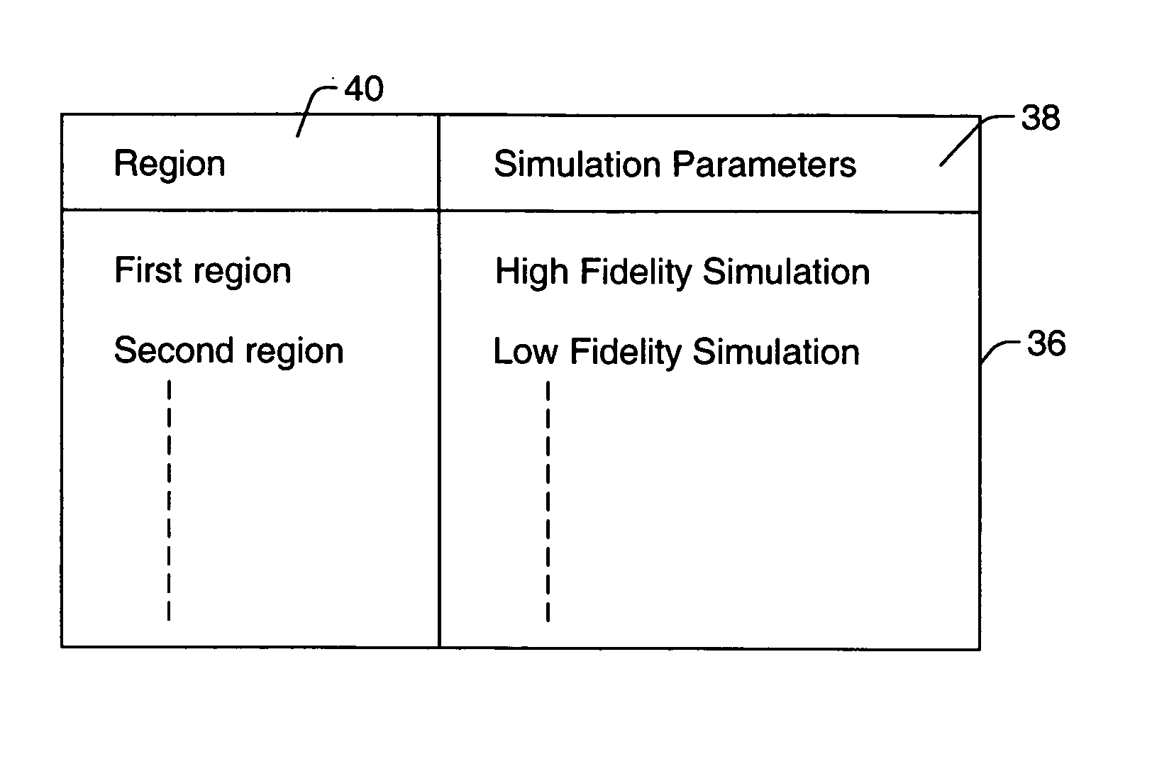
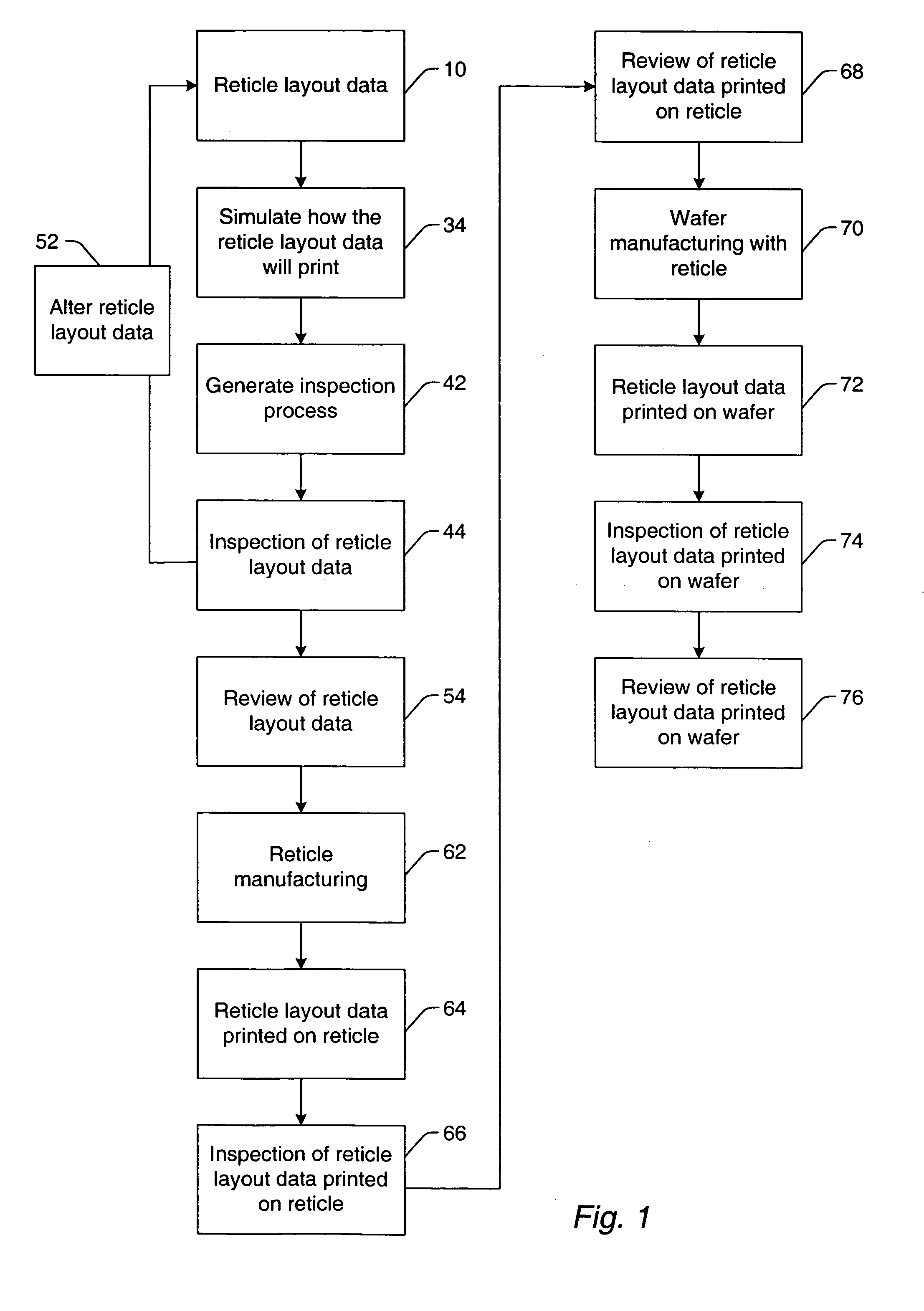
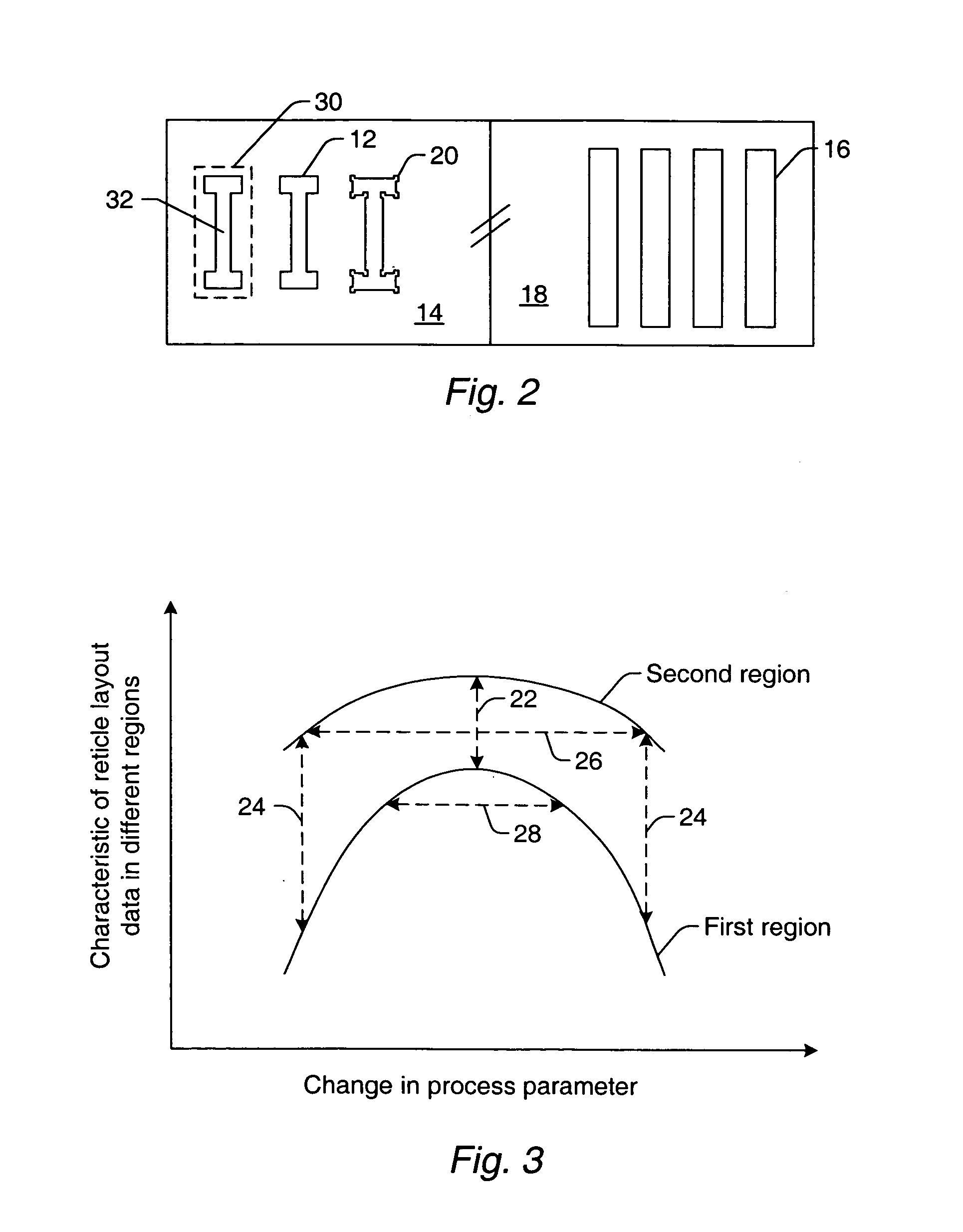
Various computer-implemented methods are provided. One method for generating a process for inspecting reticle layout data includes identifying a first region in the reticle layout data. A printability of the first region is more sensitive to changes in process parameters than a printability of a second region in the reticle layout data. The method also includes assigning one or more inspection parameters to the first region and the second region such that the first region will be inspected during the process with a higher sensitivity than the second region. Another method includes inspecting the first region with a higher sensitivity than the second region. An additional method includes simulating how the reticle layout data will print. Simulation of the first and second regions is performed with one or more different simulation parameters such that the first region is simulated with a higher fidelity than the second region.

Description

PRIORITY CLAIM [0001] This application claims priority to U.S. Provisional Application No. 60 / 526,881 entitled “Designer Intent,” filed Dec. 4, 2003, which is incorporated by reference as if fully set forth herein.BACKGROUND OF THE INVENTION [0002] 1. Field of the Invention [0003] The present invention generally relates to computer-implemented methods for simulating reticle layout data, inspecting reticle layout data, and generating a process for inspecting reticle layout data. Certain embodiments relate to a computer-implemented method that includes identifying a first region in reticle layout data that has a printability that is more sensitive to changes in process parameters than a printability of a second region in the reticle layout data. [0004] 2. Description of the Related Art [0005] The following description and examples are not admitted to be prior art by virtue of their inclusion in this section. [0006] Designing an integrated circuit (IC) involves creating a schematic des...

Claims


Application Information

Patent Timeline
Patent Type & Authority Applications(United States)
IPC IPC(8): G03F1/00G03F1/14
CPCG03F1/144G03F1/84G03F1/36
Inventor HESS, CARLXIONG, YALIN
Owner KLA TENCOR TECH CORP
Why Eureka
Try Eureka