Tuned potential pedestal for mask etch processing apparatus

a technology of etching apparatus and etching plate, which is applied in the direction of coating, chemical vapor deposition coating, electric discharge tube, etc., can solve the problems of reducing the power of the etching plate, reducing the etching plate, and reducing the etching plate. , to achieve the effect of enhancing the plasma etching process, and reducing the etching pla

Inactive Publication Date: 2005-06-23
APPLIED MATERIALS INC
View PDF31 Cites 128 Cited by
  • Summary
  • Abstract
  • Description
  • Claims
  • Application Information

AI Technical Summary

Benefits of technology

[0015] The pedestal defines a body, and a base along on an upper surface of the body. The body receives an RF power during substrate processing. The substrate support base has an outer edge, and an intermediate substrate support ridge for receiving and supporting the substrate. At least a portion of the substrate support base outside of the intermediate substrate support ridge is fabricated from a dielectric material, or material having

Problems solved by technology

However, the photoresist layer is only selectively exposed.
This limitation is compounded by a gap typically existing between the reticle and the supporting pedestal therebelow.
In addition, when the surface area of the pedestal is large compared to the reticle area, the RF power may preferentially couple to othe

Method used


Image

  • Tuned potential pedestal for mask etch processing apparatus
  • Tuned potential pedestal for mask etch processing apparatus
  • Tuned potential pedestal for mask etch processing apparatus

Examples


Embodiment Construction

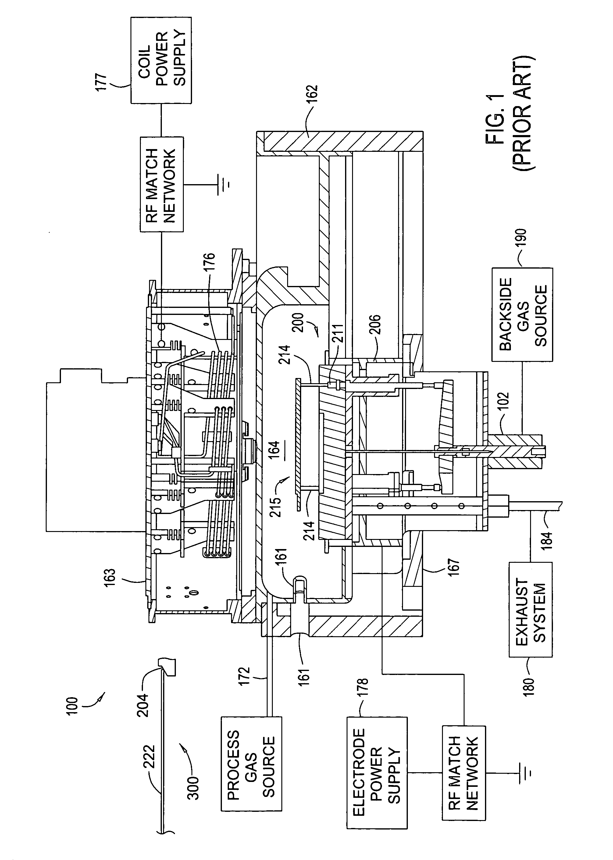
[0023] Aspects of the invention will be described below in reference to an inductively coupled plasma etch chamber. Suitable inductively coupled plasma etch chambers include the Decoupled Plasma Source (DPS™) chamber available from Applied Materials, Inc., of Santa Clara, Calif., or the ETEC Tetra™ photomask etch chamber available from ETEC of Hayward, Calif. A two-coil chamber, such as the Tetra II™ decoupled plasma source chamber available from Applied Materials, Inc. may also be employed. Other process chambers may be used including, for example, capacitively coupled parallel plate chambers and magnetically enhanced ion etch chambers, as well as inductively coupled plasma etch chambers of different designs. Although the processes are advantageously performed with the DPS™ processing chamber, the description in conjunction with the DPS™ processing chamber is illustrative and should not be construed or interpreted to limit the scope of aspects of the invention.

[0024] In order to p...


PUM

PropertyMeasurementUnit
Thicknessaaaaaaaaaa
Dielectric polarization enthalpyaaaaaaaaaa
Poweraaaaaaaaaa

Abstract

The present invention generally provides an improved pedestal for supporting a substrate. The pedestal has greatest application during a plasma etching process, such as for a quartz photomask, or “reticle.” The pedestal defines a body, and a substrate support base along an upper surface of the body. The substrate support base has an outer edge, and an intermediate substrate support ridge for receiving and supporting the substrate. At least a portion of the substrate support base outside of the intermediate substrate support ridge is fabricated from a dielectric material. The purpose is to couple greater RF power through the reticle in order to enhance the plasma etching process.

Description

CROSS-REFERENCE TO RELATED APPLICATIONS [0001] The present application claims priority to previously filed provisional patent application Ser. No. 60 / 531,062, filed Dec. 19, 2003, entitled “Tuned Potential Pedestal for Mask Etch Processing Apparatus.” The provisional application is incorporated herein by referenced in its entirety.BACKGROUND OF THE INVENTION [0002] 1. Field of the Invention [0003] The present invention generally relates to the fabrication of integrated circuits. More specifically, the invention relates to an apparatus for manufacturing a photomask, or “reticle,” useful in manufacturing semiconductors. [0004] 2. Description of the Related Art [0005] Integrated circuits (IC) are manufactured by forming discrete semiconductor devices on a surface of a semiconductor substrate. An example of such a substrate is a silicon (Si) or silicon dioxide (SiO2) wafer. To interconnect the devices on the substrate, a multi-level network of interconnect structures is formed. Material...

Claims


Application Information

Patent Timeline
IPC IPC(8): C23C16/458H01L21/00H01L21/687
CPCH01J37/321H01J2237/2001H01L21/68785H01L21/68735H01L21/67069
Inventor SATITPUNWAYCHA, PETERNGUYEN, KHIEMMAK, ALFRED W.COLLINS, KENNETH S.SAHIN, TURGUT
Owner APPLIED MATERIALS INC
Why Eureka
Try Eureka