

Semiconductor device and a manufacturing method of the same
a manufacturing method and semiconductor technology, applied in the field of semiconductor device manufacturing, can solve the problems of lens materials and resists being developed, the performance of a photolithography device has become insufficient for the pattern size required, and the development of enormous development costs
- Summary
- Abstract
- Description
- Claims
- Application Information
AI Technical Summary
Benefits of technology
Problems solved by technology
Method used
Image

Examples
fourth embodiment
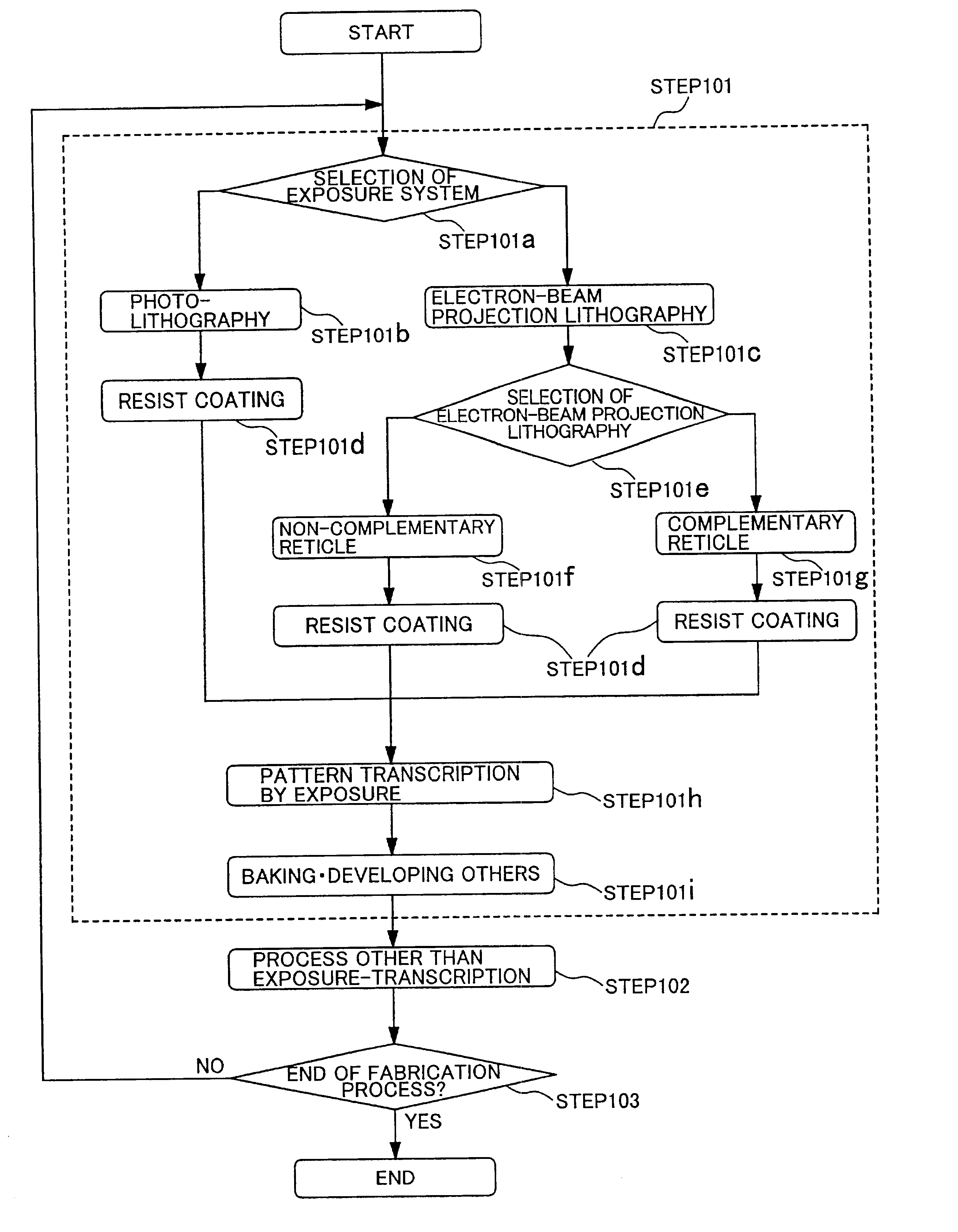
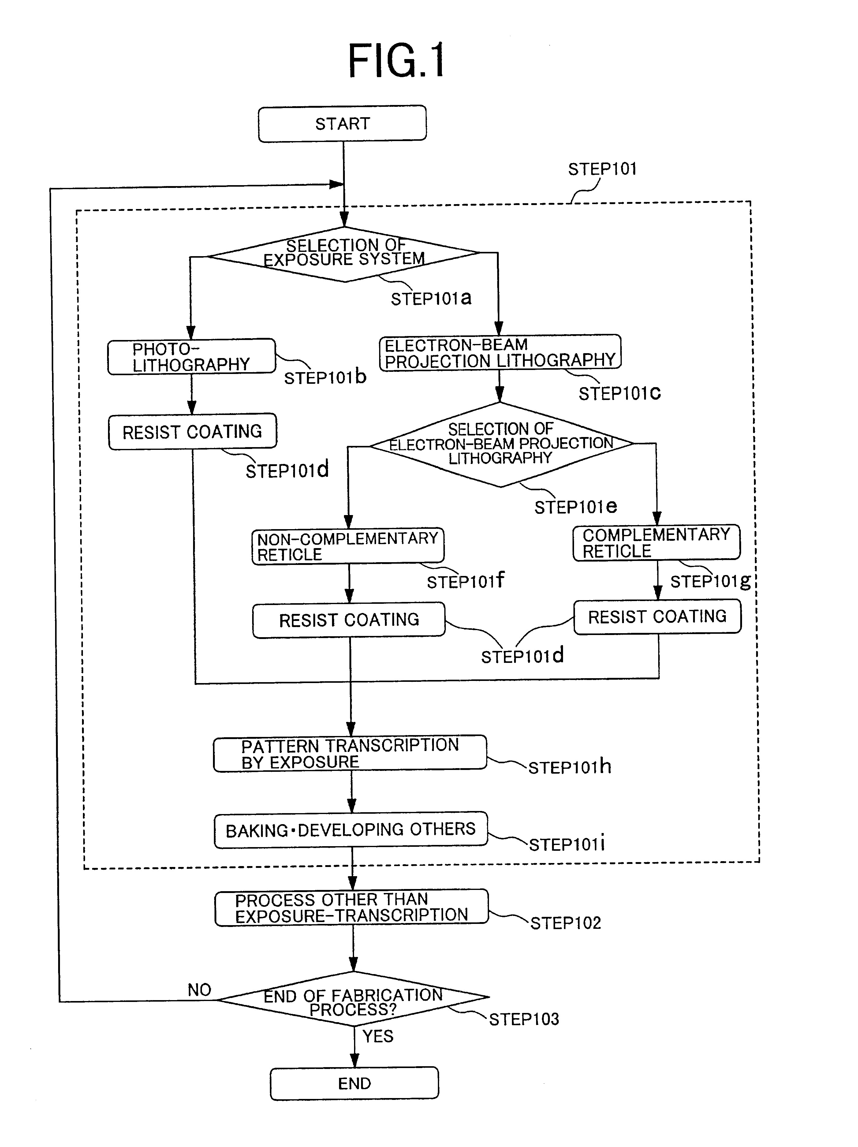
(Fourth Embodiment)
Next, by referring to FIGS. 7A to 7H, description will be made of a micro-beam forming place according to an embodiment of the present invention. FIG. 7A shows a design pattern. If a reticle is manufactured directly with this design data, bending easily occurs at a corner 704a of a non-opening pattern because stress is released. FIGS. 7B to 7H show examples of measures taken to deal with this bending. In FIG. 7B, a predetermined pattern is divided into rectangles, one or both of intersected portions of rectangular patterns are reduced by predetermined amounts, and a micro-beam 701bis formed. This method can be easily carried out by using conventional design automation (DA). In FIG. 7C, a downsizing amount of an area having a high pattern density is increased, for example at an intersected portion of patterns, increasing a size of a micro-beam 701C. In the area of a high pattern density, back scattering makes it difficult to project a micro-beam even if the micro-b...
fifth embodiment
(Fifth Embodiment)
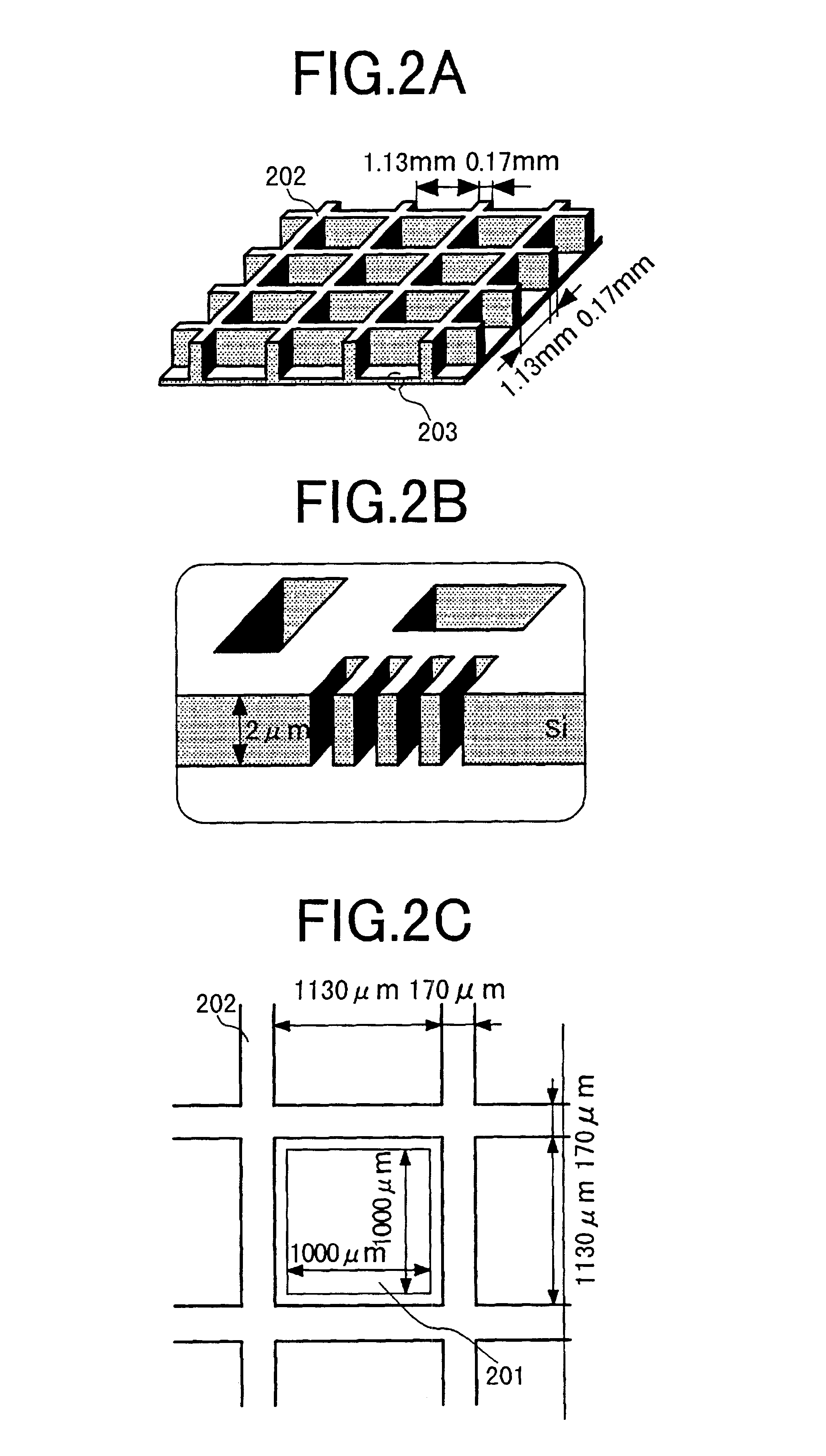
Next, an example of applying a micro-beam to a doughnut type pattern is described. As shown in FIG. 8A, since nothing is present to support a non-opening area 801 in an opening area 802, the doughnut type pattern itself cannot be independent. Accordingly, for example as shown in FIGS. 8B and 8C, the non-opening area can be supported by providing a micro-beam 803 at a corner of the opening area. This is because in the opening area similar to an area of a high pattern density, e.g., at a corner exceeding 180.degree., back scattering makes it difficult to project the micro-beam as in the case of the fourth embodiment. Other than FIGS. 8B and 8C, by a combination with a micro-beam made in the third embodiment, the doughnut type pattern can be dealt with. Moreover, the number of micro-beams is small, i.e., 4, in FIG. 8B, and thus it is possible to suppress dense disposition of patterns.
On the other hand, the number of micro-beams is 8 in FIG. 8C. Accordingly, a mechanic...
sixth embodiment
(Sixth Embodiment)
Next, description will be made of an embodiment of applying the present invention to a continuous doughnut type patterns by referring to FIGS. 9A to 9D. As shown in FIG. 9A, the combinations of the third to fifth embodiments can be used also for the continuous doughnut type pattern. In FIG. 9B, an opening area 902 of FIG. 9A is divided into rectangular patterns, and a micro-beam 903b is formed at a connection portion between the rectangular patterns. This method facilitates formation of micro-beams. In FIG. 9C, a width of a micro-beam 903c in a place where one rectangular pattern is in contact with three or more rectangular patterns on the doughnut type pattern is set larger than that of another micro-beam 904c. In this case, a pattern size is 300 nm, and a size of the micro-beam 903c is set to 35 nm while that of the micro-beam 904c is 25 nm. In the place where one rectangular pattern is in contact with three or more rectangular patterns, a proximity effect makes ...
PUM
| Property | Measurement | Unit |
|---|---|---|
| size | aaaaa | aaaaa |
| length | aaaaa | aaaaa |
| sizes | aaaaa | aaaaa |
Abstract
Description
Claims
Application Information