Avionics chassis

a chassis and aircraft technology, applied in the field of aircraft chassis, can solve problems such as weight increas

Active Publication Date: 2011-03-22
GENERAL ELECTRIC CO
View PDF71 Cites 18 Cited by
  • Summary
  • Abstract
  • Description
  • Claims
  • Application Information

AI Technical Summary

Problems solved by technology

The performance of the beneficial functions is often inapposite to maintaining or reducing the weight of the avionics chassis, especially in light of newer avionics having faster processing speeds and higher frequencies, smaller size, and greater power densities.
These avionics generate relatively large amounts of heat, but operate only under a certain range of threshold temperatures, which leads to an increased heat-dissipating requirement that has been previously addressed by increasing the size of the heat sink, leading to an increased weight.

Method used


Image

  • Avionics chassis
  • Avionics chassis
  • Avionics chassis

Examples


Embodiment Construction

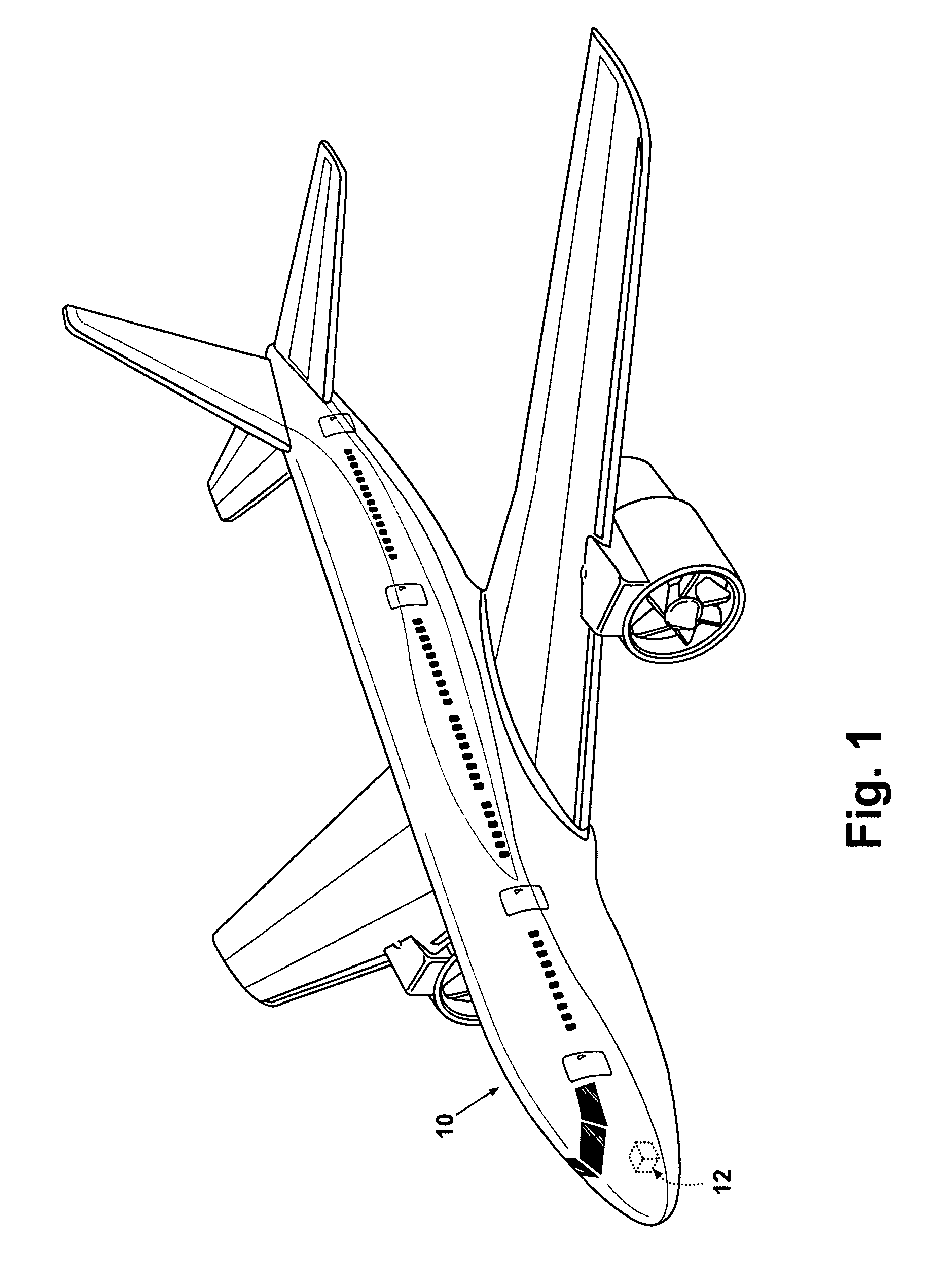
[0021]FIG. 1 schematically illustrates an aircraft 10 with an on-board avionics chassis 12 (shown in phantom) for housing avionics for use in the operation of the aircraft 10. The avionics chassis 12 houses a variety of avionics elements and protects them against contaminants, electromagnetic interference (EMI), radio frequency interference (RFI), vibrations, and the like. While illustrated in a commercial airliner, the avionics chassis 12 can be used in any type of aircraft, for example, without limitation, fixed-wing, rotating-wing, rocket, commercial aircraft, personal aircraft, and military aircraft. The avionics chassis 12 may be located anywhere within the aircraft, not just the nose as illustrated.

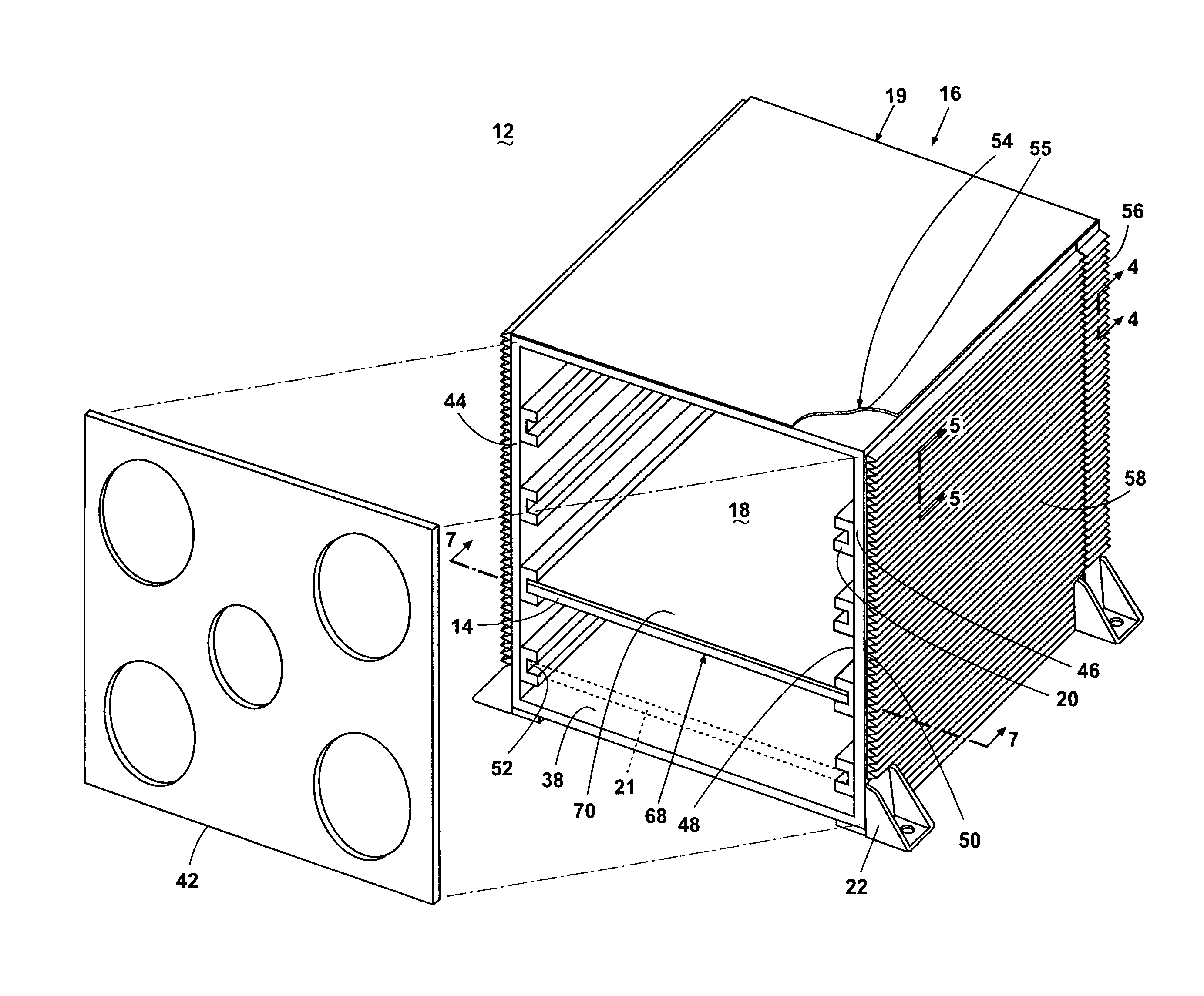
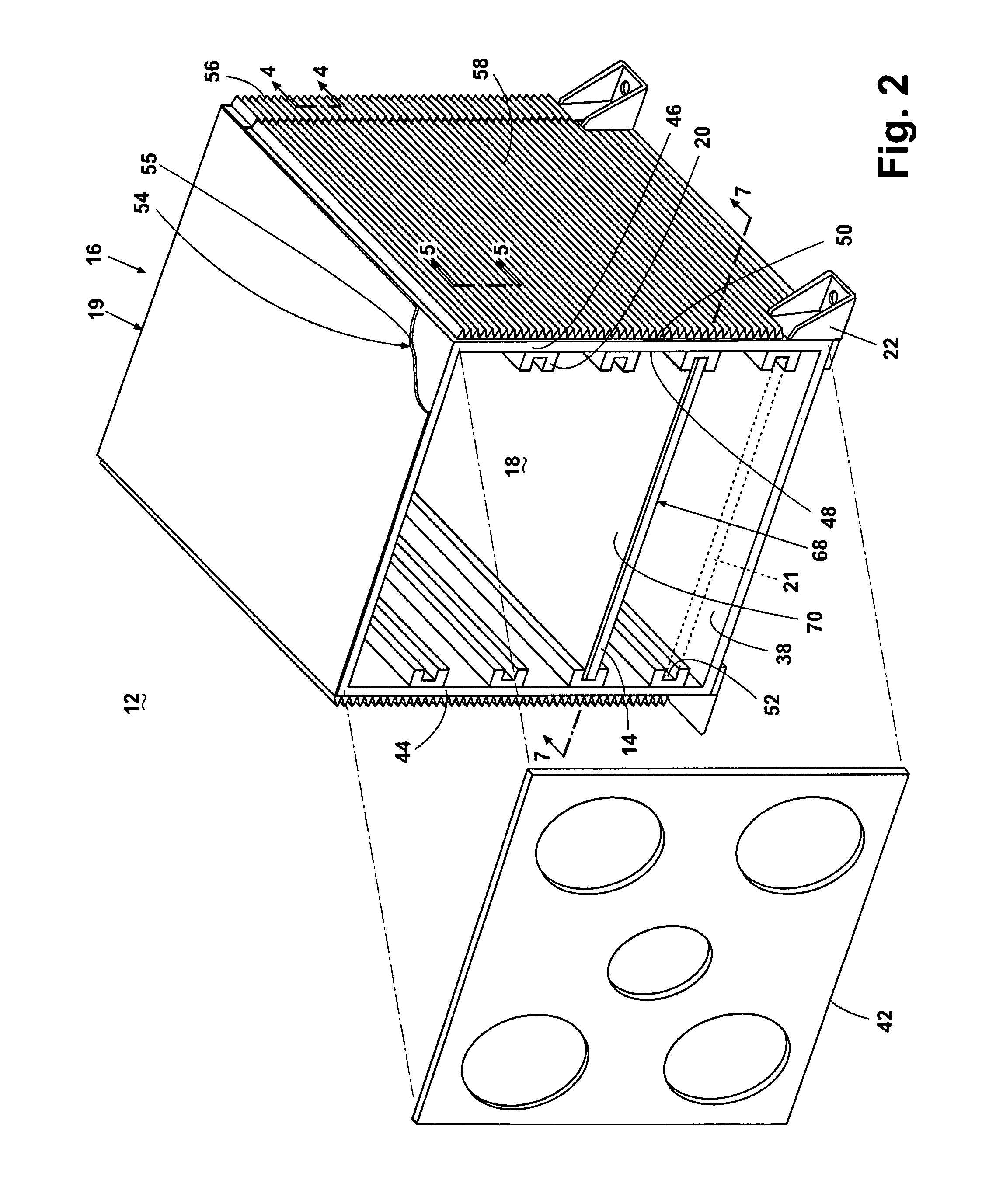
[0022]FIG. 2 illustrates the avionics chassis 12 according to one embodiment of the invention, with a front cover 42 removed. The avionics chassis 12 includes a chassis housing 16 that defines an interior 18 and exterior 19. Pluralities of thermally conductive card rails 20 define e...


PUM


Abstract

An avionics chassis comprises a housing having a substantially thermally non-conductive frame comprising a composite of carbon fibers laid up in an epoxy matrix. The housing also includes at least two walls, at least one of which is a thermally conductive wall comprising a composite of carbon fibers in a carbonized matrix, and a plurality of spaced, thermally-conductive, card rails provided on the at least two walls. The at least two walls are mounted to the frame in opposing relationship such that corresponding card rails on the walls define an effective slot therebetween in which a printed circuit board may be received and the card rails and the at least one thermally conductive wall form a thermally conductive path from the interior to the exterior.

Description

GOVERNMENT LICENSE RIGHTS[0001]This invention was made with Government support under Purchase Order No. 4CC1766 awarded by Department of the Air Force, Air Force Research Laboratory. The Government has certain rights in this invention.CROSS-REFERENCE TO RELATED APPLICATIONS[0002]This application is related to patent application Ser. No. 12 / 487,784, entitled Avionics Chassis, patent application Ser. No. 12 / 487,797, entitled Avionics Chassis, and patent application Ser. No. 12 / 487,834, entitled Avionics Chassis, filed concurrently herewith.BACKGROUND OF THE INVENTION[0003]Contemporary aircrafts use avionics in order to control the various equipment and operations for flying the aircraft. The avionics may be stored in an avionics chassis, which performs several beneficial functions, some of which are: electrically shielding the avionics from electromagnetic interference (EMI), protecting the avionics from lightning strikes, dissipating the heat generated by the avionics, and protecting...

Claims


Application Information

Patent Timeline
Patent Type & Authority Patents(United States)
IPC IPC(8): H05K7/20
CPCH05K7/1412H05K9/0062H05K7/20545H05K7/183
Inventor VANDER PLOEG, BENJAMIN JONSTEENWYK, MEREDITH MARIECOXON, DANNY WELDONSTREYLE, JOHN JAY
Owner GENERAL ELECTRIC CO
Why Eureka
Try Eureka