
Complex coefficient transversal filter and complex frequency converter

a filter and complex technology, applied in the field of complex coefficient transversal filter and complex frequency converter, can solve the problems of deterioration of circuit size increase, second-order inter-modulation distortion, etc., to improve image suppression characteristic, improve error vector magnitude (evm) characteristic, good image suppression characteristi

Inactive Publication Date: 2011-03-22
SAMSUNG ELECTRONICS CO LTD
View PDF19 Cites 0 Cited by
  • Summary
  • Abstract
  • Description
  • Claims
  • Application Information

AI Technical Summary

Benefits of technology

[0016]An aspect of exemplary embodiments of the present invention is to address at least the above problems and / or disadvantages and to provide at least the advantages described below. Accordingly, an aspect of exemplary embodiments of the present invention is to provide a complex coefficient transversal filter capable of maintaining a phase difference between real and imaginary components to be 90° without a phase shift and obtaining a good image suppression characteristic, so that it is possible to improve an error vector magnitude (EVM) characteristic of a zero-IF frequency converter and to improve an image suppression characteristic of a low-IF frequency converter.

Problems solved by technology

In such a multi-mode transceiver, since separate IF filters are needed in order to provide different channel bandwidths for different modes, a problem exists in that a circuit size increases greatly.
However, in the zero-IF system, since the RF signal is converted into a baseband signal, an IM2 problem exists, that is, a problem of second-order inter-modulation distortion caused by DC offset after frequency conversion and nonlinearity of a mixer.
In turn, a problem of deterioration in an error vector magnitude (EVM) characteristic exists.
However, due to incompleteness of an analog circuit, there is a limitation to improve the errors between I and Q. For example, in multi-level modulation, a deterioration caused by interference between symbols exists, and in an orthogonal frequency division multiplexing (OFDM), a problem of interference between carriers exists.
In a multiple-input multiple-output (MIMO) system, which is a type of communication system in a wireless LAN due to the incompleteness of the analog circuit, a limitation to increase communication speed exists.
Although the frequency can be fixed, the frequency band cannot be fixed.
However, in a conventional low-IF system, the image suppression ratio is about 30 dB (see Phillips Datasheets SA1920 and SA1921), which is too low.
However, the conventional low-IF system cannot be used for a system requiring an image suppression ratio exceeding 30 dB.

Method used


Image

  • Complex coefficient transversal filter and complex frequency converter
  • Complex coefficient transversal filter and complex frequency converter
  • Complex coefficient transversal filter and complex frequency converter

Examples


Embodiment Construction

[0033]The matters defined in the description such as a detailed construction and elements are provided to assist in a comprehensive understanding of exemplary embodiments of the invention. Accordingly, those of ordinary skill in the art will recognize that various changes and modifications of the embodiments described herein can be made without departing from the scope and spirit of the invention. Also, descriptions of well-known functions and constructions are omitted for clarity and conciseness.

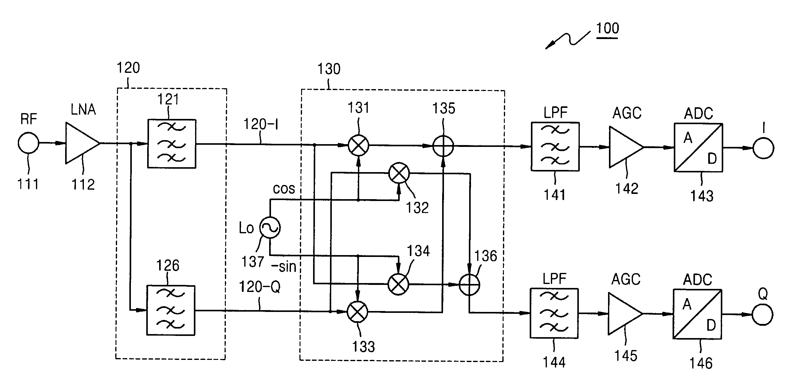
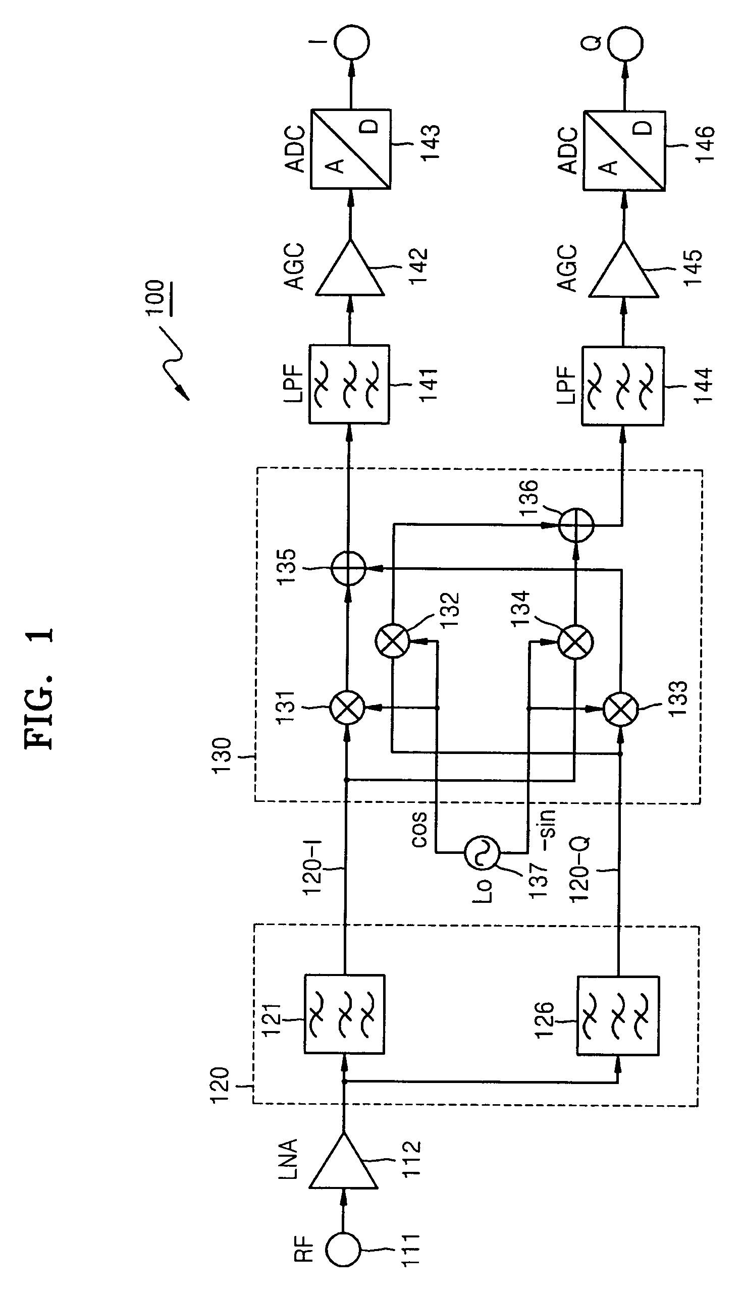
[0034]FIG. 1 is a schematic view showing a construction of a complex frequency converter 100 according to an exemplary embodiment of the present invention.

[0035]The complex frequency converter 100 according to an exemplary embodiment of the present invention includes an antenna 111, a low noise amplifier (LNA) 112, a complex coefficient transversal filter 120, a complex mixer 130, low pass filers (LPFs) 141 and 144, automatic gain controllers (AGCs) 142 and 145, and analog-to-digital conver...


PUM


Abstract

A complex coefficient transversal filter using a SAW filter and a complex frequency converter using the complex coefficient transversal filter are provided, in which a first SAW filter receives a real signal as an input signal and generates a real component of a complex signal, and a second SAW filter receives the real signal as an input signal and generates an imaginary component of the complex signal. Accordingly, feed-through waves between the input and output stages can be cancelled, and a phase difference between real and imaginary signals can be maintained at 90° without a phase shift. In addition, when a low-IF frequency converter is implemented using the complex coefficient transversal filter, an image suppression characteristic is improved. When a zero-IF frequency converter is implemented using the complex coefficient transversal filter, an error vector magnitude (EVM) characteristic is improved.

Description

CROSS-REFERENCE TO RELATED PATENT APPLICATION[0001]This application claims the benefit under 35 U.S.C. §119(a) of Japanese Patent Application No. 2005-363175, filed on Dec. 16, 2005, in the Japanese Intellectual Property Office, and the benefit of Korean Patent Application No. 10-2006-0102037, filed on Oct. 19, 2006, in the Korean Intellectual Property Office, the entire disclosures of both of which are hereby incorporated by reference.BACKGROUND OF THE INVENTION[0002]1. Field of the Invention[0003]The present invention relates to a complex coefficient transversal filter and a complex frequency converter. More particularly, the present invention relates to a complex coefficient transversal filter using a surface acoustic wave (SAW) filter suitable for implementing a high-frequency complex coefficient filter for a high-performance radio communication terminal and a complex frequency converter using the complex coefficient transversal filter.[0004]2. Description of the Related Art[000...

Claims


Application Information

Patent Timeline
Patent Type & Authority Patents(United States)
IPC IPC(8): H04L27/00
CPCH03H9/02818H03H9/02952H03H9/6433H03H9/68H03D7/18H03H15/00
Inventor SATO, TAKAHIROSUGIURA, TSUYOSHI
Owner SAMSUNG ELECTRONICS CO LTD
Learn More