Acoustic wave filter manufacturing method using photo-definable epoxy for suppression of unwanted acoustic energy

a technology of acoustic energy suppression and manufacturing method, which is applied in the direction of electrical transducers, impedence networks, electrical apparatus, etc., can solve the problems of inability to design precise or specific acoustic desirable patterns, inability to meet the needs of acoustic interference, etc., to achieve the effect of improving the error vector magnitude (evm) of the if filter, improving the fidelity of the radio

Active Publication Date: 2015-10-20
QORVO US INC
View PDF11 Cites 0 Cited by
  • Summary
  • Abstract
  • Description
  • Claims
  • Application Information

AI Technical Summary

Benefits of technology

[0011]The teachings of the present invention provide a new way of applying an epoxy based photo-definable photo resist for providing an acoustic absorption of unwanted reflections present on the surface of a piezoelectric substrate. A photo imagable epoxy is used as an absorber and has been shown to provide desirable transmission capability as a screen absorber. In addition, remarkable performance improvement over typical screen absorbers in terms of its reflection capability, specifically over a cold temperature range has been experienced. As a result, an Error Vector Magnitude (EVM) of an IF filter is improved at cold temperatures, thus improving fidelity of a radio receiver for digital based communication systems, by way of example. The photo definable absorber according to the teachings of the present invention is further compatible with a standard semiconductor photolithography process allowing the process flow to be streamlined and decreasing the overall cost.

Problems solved by technology

One major drawback of RTV is that the method of application wherein material is typically forced out through a syringe is very coarse, thus not allowing designers to lay out a precise or specific acoustically desirable pattern.
However, this method has several disadvantages.
As a result, it becomes very difficult to design high performance intermediate frequency (IF) filters on packages smaller than 5×5 mm.
Further, the performance of this absorber material at cold temperature is inadequate for several filters with low error vector magnitude (EVM) as has been reported by device users and design engineers.
The lack of performance is due to the fact that this material becomes stiff and rigid at cold temperature.
Yet further, the typical absorber application method is not compatible with a standard semiconductor photolithography process.
The current screen printing method increases overall wafer level manufacturing costs because of the requirement that an operator be employed to manually align the absorber mask with the patterned wafers.
In addition, the normal process is disrupts the normal process flow that needs to be streamlined to avoid all possible manufacturing mistakes.
Typical methods making use of polymers that can be photo-definable suffer from poor absorption of acoustic wave energy and thus have limited usage.

Method used


Image

  • Acoustic wave filter manufacturing method using photo-definable epoxy for suppression of unwanted acoustic energy
  • Acoustic wave filter manufacturing method using photo-definable epoxy for suppression of unwanted acoustic energy
  • Acoustic wave filter manufacturing method using photo-definable epoxy for suppression of unwanted acoustic energy

Examples


Embodiment Construction

[0021]The present invention will now be described more fully hereinafter with reference to the accompanying drawings, in which embodiments of the invention are shown. This invention may, however, be embodied in many different forms and should not be construed as limited to the embodiments set forth herein. Rather, these embodiments are provided so that this disclosure will be thorough and complete, and will fully convey the scope of the invention to those skilled in the art.

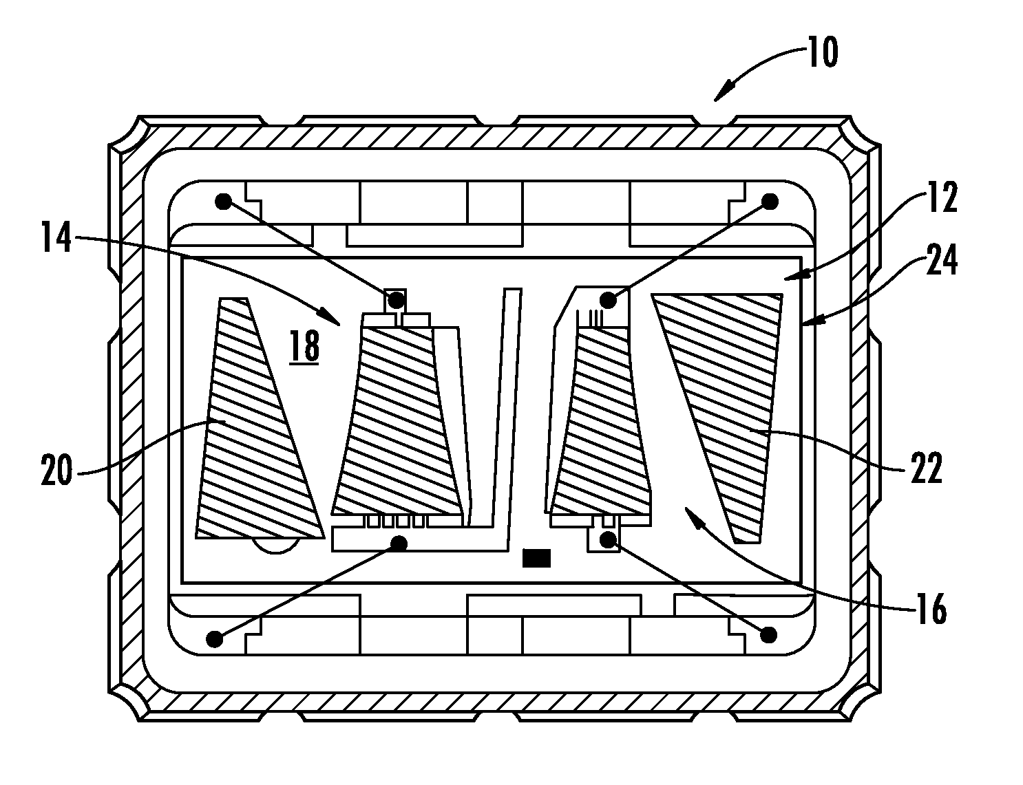
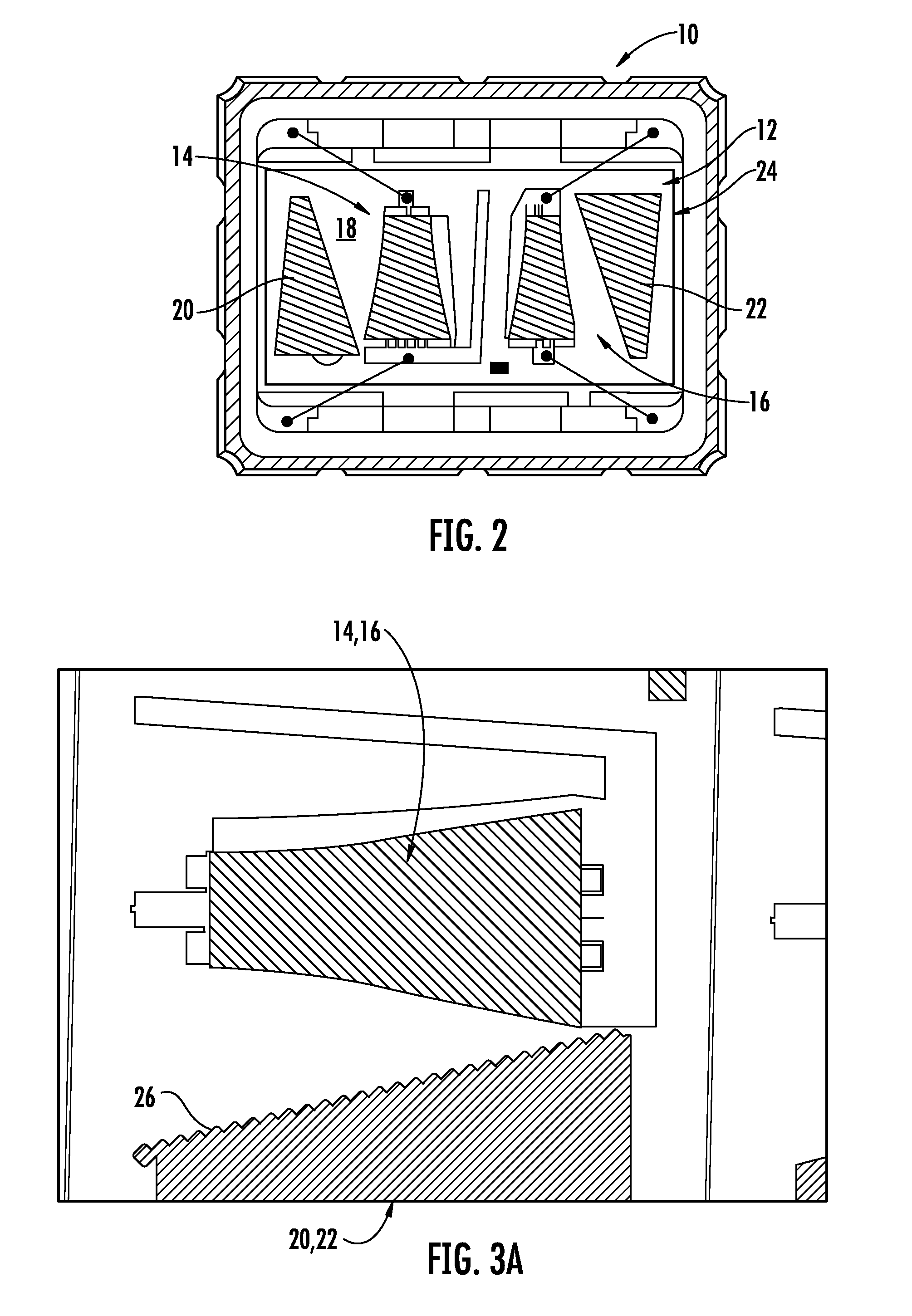
[0022]With reference now to FIG. 2, one embodiment of the present invention comprises a SAW filter 10 comprising a substrate 12 and input and output transducers 14, 16 on a surface 18 of the substrate. For the embodiment herein described by way of example with reference to FIG. 2, an epoxy based photo-definable absorber material 20, 22 is carried on the surface 18 at opposing ends of the transducers 14, 16. The epoxy based photo-definable absorber material 20, 22 is herein defined for an absorber of an epoxy base...


PUM


Abstract

A SAW filter is fabricated with input and output transducers on a piezoelectric substrate and an epoxy based photo-definable acoustic absorber on the substrate for suppressing unwanted acoustic waves. The photo-definable acoustic absorber has a viscosity in a range from about 50 centistokes to 12000 centistokes and a thickness from about 10 microns to 120 microns. One acoustic absorber includes an SU-8 family member epoxy.

Description

CROSS-REFERENCE TO RELATED APPLICATIONS[0001]This application is a divisional of U.S. application Ser. No. 12 / 277,415, filed Nov. 25, 2008, now U.S. Pat. No. 7,800,281, which is commonly owned.FIELD OF INVENTION[0002]The present invention generally relates to the field of acoustic wave devices using piezoelectric substrates, and more particularly to an acoustic wave device employing acoustic absorbers for suppression of unwanted acoustic energy.BACKGROUND[0003]It is a well recognized practice to apply some sort of acoustic absorber material at the ends of the piezoelectric surface and also on certain portions of the metal transducers as well as the multi-strip coupler of a surface acoustic wave (SAW) filter, by way of example. By absorbing undesired modes of the SAW, both the frequency response of the filter as well as side lobes and the rejection of various time spurious responses such as edge reflections may be significantly enhanced.[0004]Typically, SAW device manufacturers use a...

Claims


Application Information

Patent Timeline
Patent Type & Authority Patents(United States)
IPC IPC(8): H04R17/00H03H9/64H03H3/007H03H3/02
CPCH03H9/64H03H3/007H03H3/02H03H9/02842
Inventor GRAMA, GEORGECOMBE, SUZANNECHANG, RODOLFO
Owner QORVO US INC
Why Eureka
Try Eureka