Sheet feeding device, sheet feeding unit and image forming apparatus connected with the sheet feeding unit with a controlled floating air blowing mechanism

a feeding device and control technology, applied in the direction of thin material processing, transportation and packaging, article separation, etc., can solve the problems of inability to judge whether the floating of the sheet is appropriate, and the inability to cope with the dispersion of the states of the same sheet typ

Active Publication Date: 2011-03-29
KONICA MINOLTA BUSINESS TECH INC
View PDF9 Cites 25 Cited by
  • Summary
  • Abstract
  • Description
  • Claims
  • Application Information

AI Technical Summary

Problems solved by technology

In the technology described in Unexamined Japanese Patent Application Publication No. 2005-75540, it is impossible to cope with dispersion of the states in the same sheet type and with an influence of the state of keeping for sheets, because conditions are fixed by the sheet type.
Further, in the technology described in Unexamined Japanese Patent Application Publication No. 2005-96993, it is impossible to judge whether floating of the sheet is appropriate or not, because a judgment is one under the state of sheet feeding.
Therefore, there have been generated dispersions on states of floating by air, and sure separation and conveyance of sheets have been impossible, resulting in problems.

Method used


Image

  • Sheet feeding device, sheet feeding unit and image forming apparatus connected with the sheet feeding unit with a controlled floating air blowing mechanism
  • Sheet feeding device, sheet feeding unit and image forming apparatus connected with the sheet feeding unit with a controlled floating air blowing mechanism
  • Sheet feeding device, sheet feeding unit and image forming apparatus connected with the sheet feeding unit with a controlled floating air blowing mechanism

Examples


Embodiment Construction

[0020]Embodiments for the sheet feeding device of the invention, the sheet feeding unit equipped with the sheet feeding device and for the image forming apparatus to which the sheet feeding unit is connected, will be explained as follows, referring to the drawings.

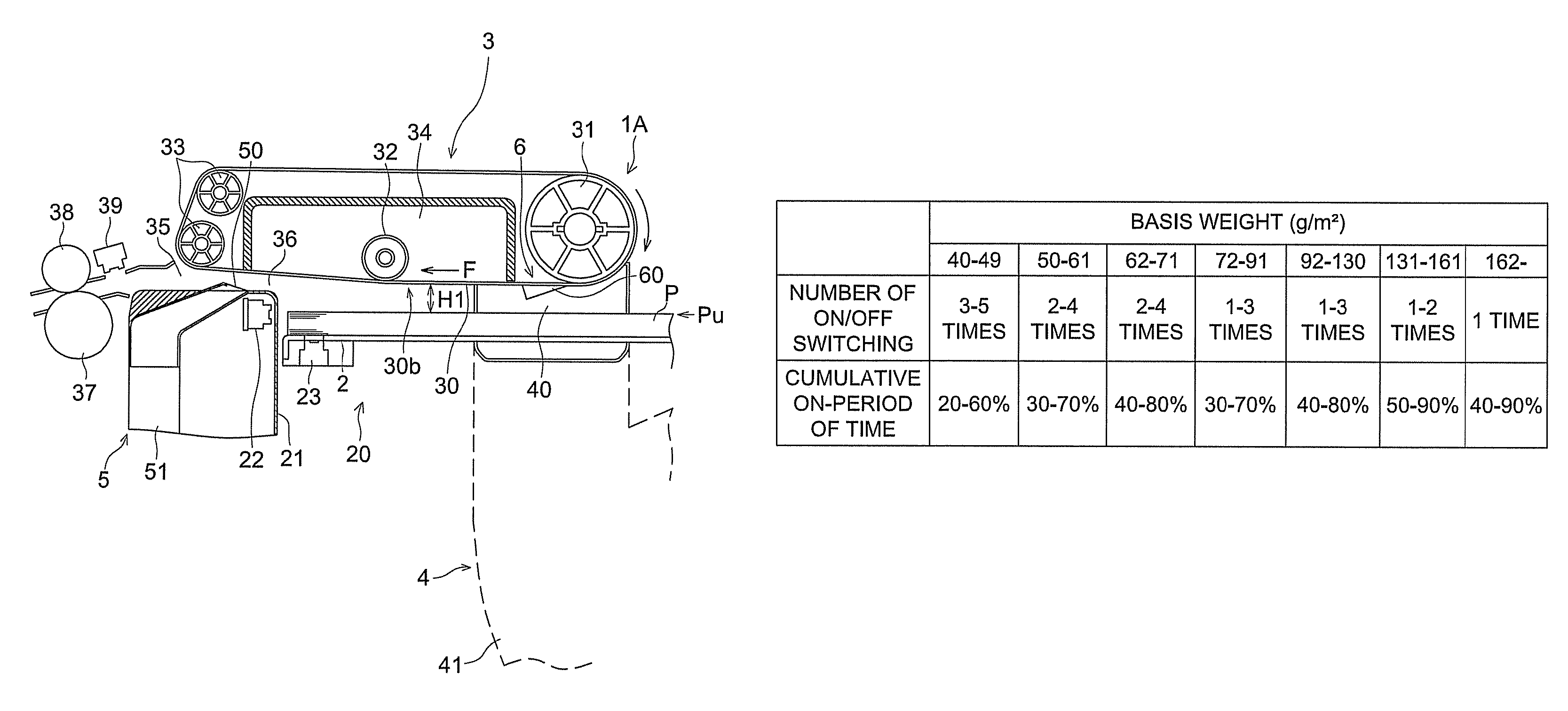
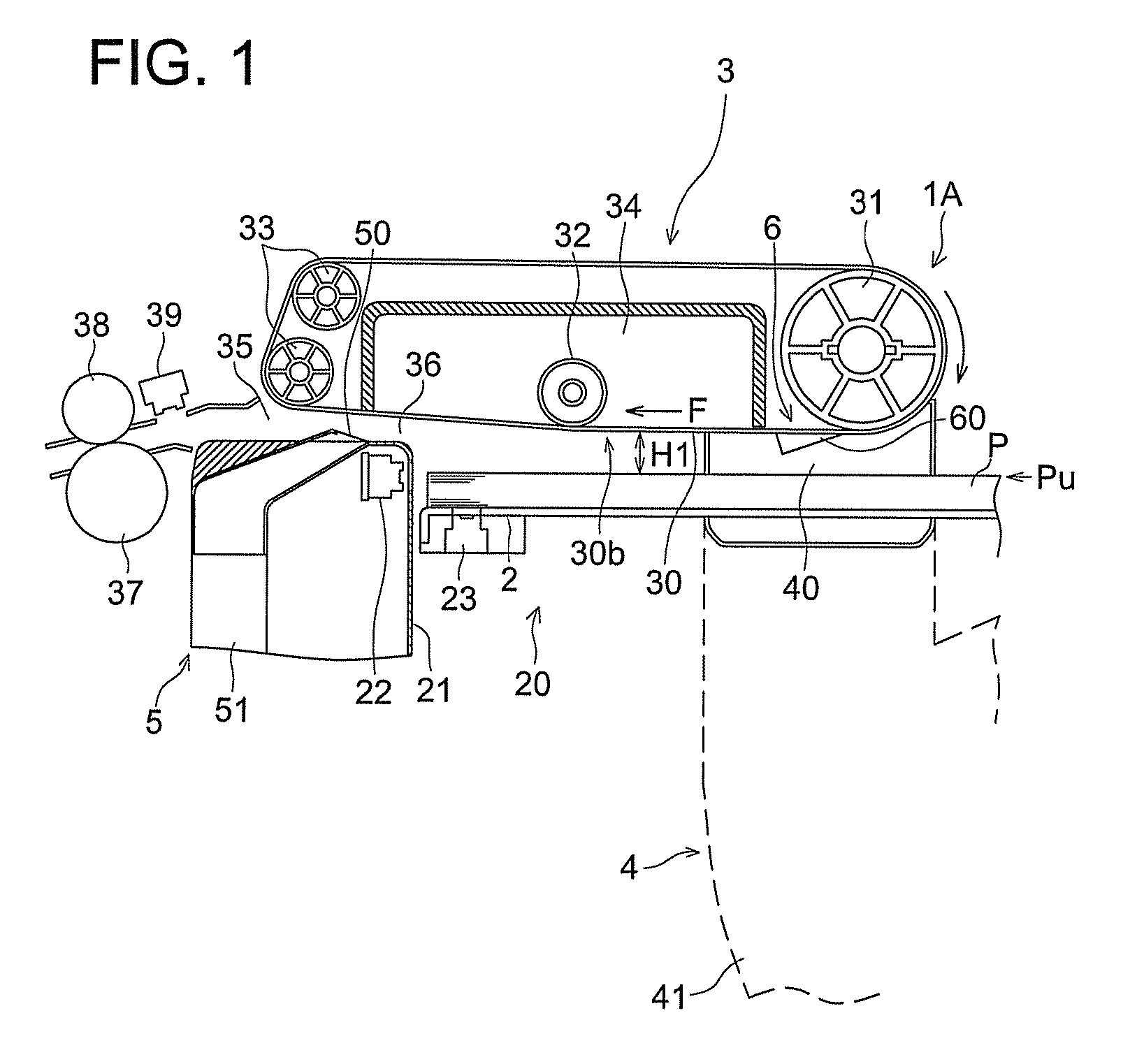
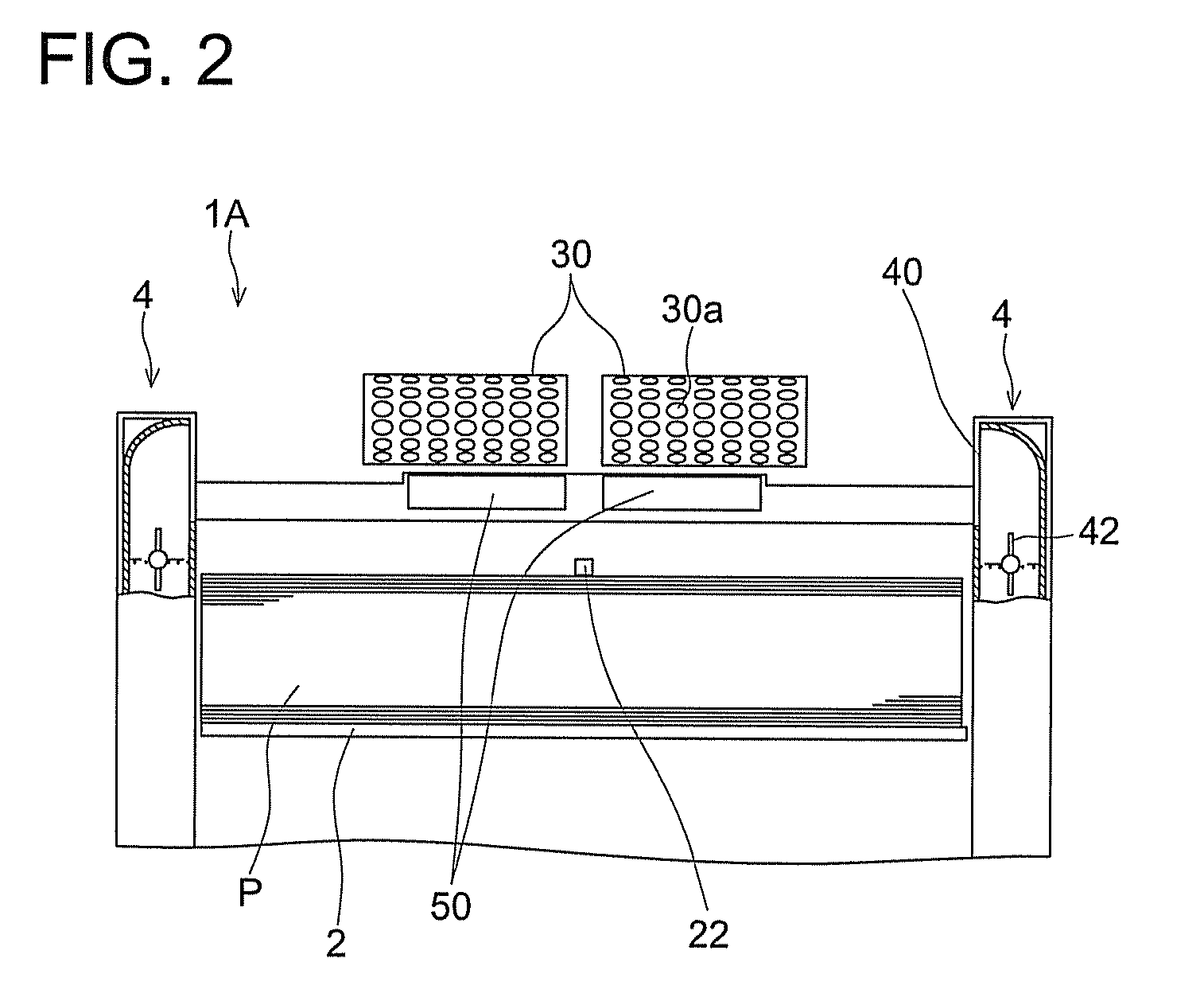
[0021]FIG. 1 is a side view showing an example of a sheet feeding device of the present embodiment, FIG. 2 is a front view showing an example of a sheet feeding device of the present embodiment and FIG. 3 is a perspective view of a sheet storage section showing an example of a sheet feeding device of the present embodiment.

[0022]The sheet feeding device 1A of the present embodiment is equipped with sucking and conveying mechanism 3 that sucks sheet P stacked on sheet stacking table 2 and feeds out and with floating air blowing mechanism 4 that blows floating air A1 against sheet P stacked on the sheet stacking table 2. Further, the sheet feeding device 1A is equipped with separation air blowing mechanism 5 that blows separ...


PUM


Abstract

A sheet feeding device may include a sucking and conveying mechanism having a suction surface, which sucks sheets stacked on a sheet stacking table, from an upper surface of the sheets, sucks an uppermost sheet to be sucked on the suction surface, and conveys the uppermost sheet onto a sheet conveyance path; a floating air blowing mechanism which blows floating air against the sheets from a side surface of the stacked sheets; a sheet position detecting sensor which detects an upper surface height position of the sheets stacked, and detects a floating state of the sheets floated; and a controller which judges the floating state of the sheets detected in a floating state detecting period in connection with a blowing of the floating air, and controls an air volume of floating air blown from the floating air blowing mechanism based on the floating state of the sheets.

Description

[0001]This application is based on Japanese Patent Application No. 2008-316053 filed on Dec. 11, 2008, which is incorporated hereinto by reference.BACKGROUND OF THE INVENTION[0002]The present invention relates to a sheet feeding device wherein sheets stacked on a sheet stacking table are sucked to a suction surface by air to be fed out, and in particular, to an object wherein an air volume of floating air is made to be reasonable based on the state of floating in the case of blowing floating air against sheets stacked on the sheet stacking table.[0003]An air sheet feeder has been used as a sheet feeding device of an image forming apparatus such as a copying machine. In the sheet feeding device, there is employed a mechanism wherein air is blown against a side edge surface of stacked sheets, and a sheet thus floated is sucked on a suction surface such as a perforated belt on which a suction opening that draws air is formed, and the belt is driven to rotate to convey the sheet.[0004]W...

Claims


Application Information

Patent Timeline
Patent Type & Authority Patents(United States)
IPC IPC(8): B65H3/14
CPCB65H3/128B65H3/48B65H2511/20B65H2511/417B65H2511/51B65H2515/342B65H2801/06B65H2220/01B65H2220/03B65H2220/02B65H2515/34
Inventor KOSUGI, AKIRAUEDA, DAISUKE
Owner KONICA MINOLTA BUSINESS TECH INC
Why Eureka
Try Eureka