Display unit

a technology for display parts and display parts, applied in the field of display parts, can solve the problems of disadvantageous reduction of the display area of the display part, and achieve the effect of improving operability and adequate display area

Active Publication Date: 2011-03-29
CATEYE
View PDF41 Cites 14 Cited by
  • Summary
  • Abstract
  • Description
  • Claims
  • Application Information

AI Technical Summary

Benefits of technology

[0008]An object of the present invention is to provide a display unit improved in operability while an adequate display area is ensured.
[0010]According to this structure, the operability for switching the display state can be improved while reduction in the area of the display part is prevented.
[0012]According to this structure, the body is pressed against the securing tool for pushing up the changeover switch, thereby switching the display state. Thus, the operability for switching the display state can be improved while reduction in the area of the display part is prevented.
[0015]Thus, the changeover switch can be prevented from a false operation resulting from vertical vibration according to either aspect.
[0017]When the rider of the two-wheeler wears gloves, it is difficult to operate a small changeover switch in particular. According to the aforementioned display unit, the rider can switch the display state by pressing a wide surface of the body, whereby a remarkable effect can be achieved in operability.
[0018]According to the present invention, as hereinabove described, a display unit improved in operability can be provided while an adequate display area is ensured.

Problems solved by technology

When the changeover switch is provided on the upper surface of the display unit, however, the display area of the display part is disadvantageously reduced.

Method used


Image

  • Display unit
  • Display unit
  • Display unit

Examples


Embodiment Construction

[0030]An embodiment of a display unit according to the present invention is now described. Identical or corresponding portions are denoted by the same reference numerals, and redundant description may not be repeated.

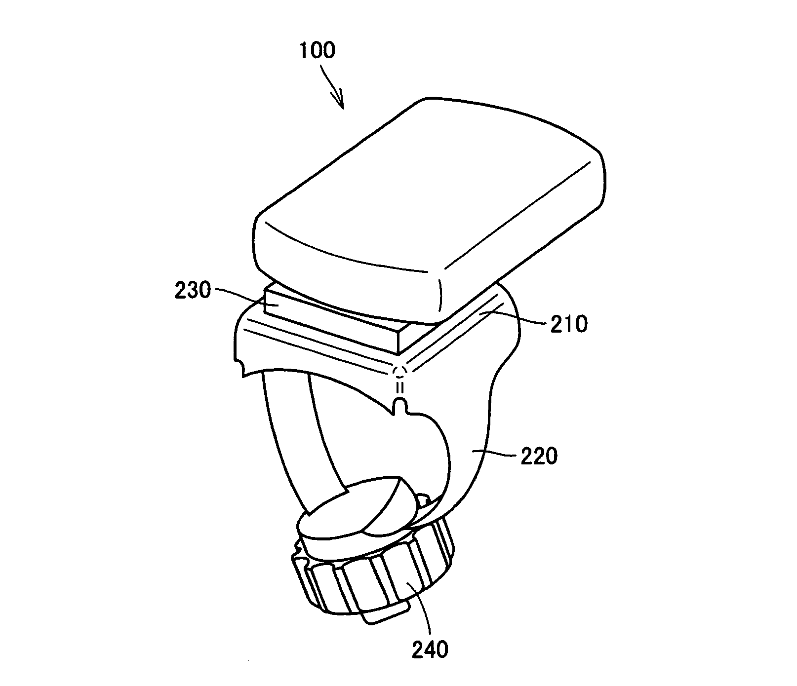
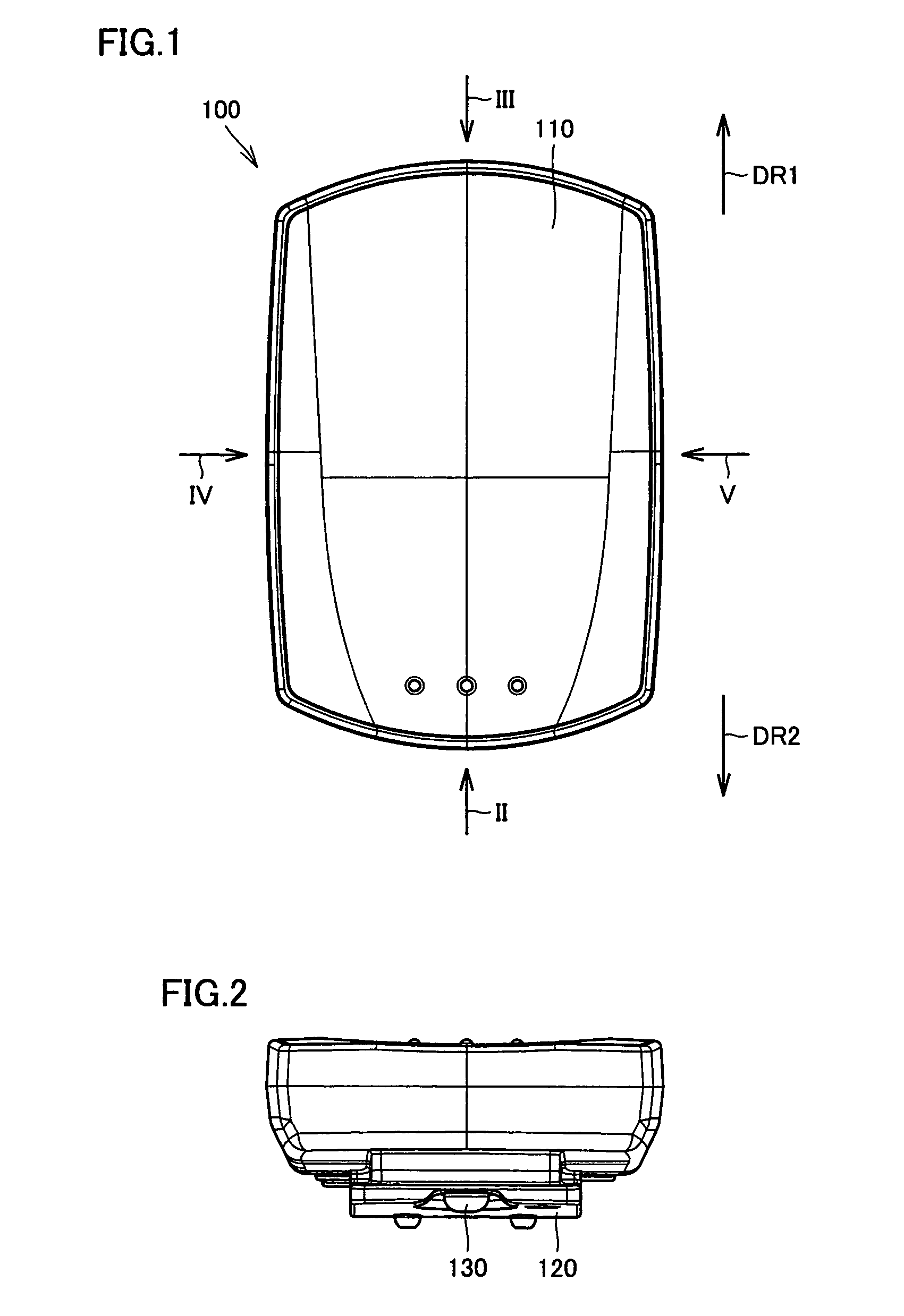
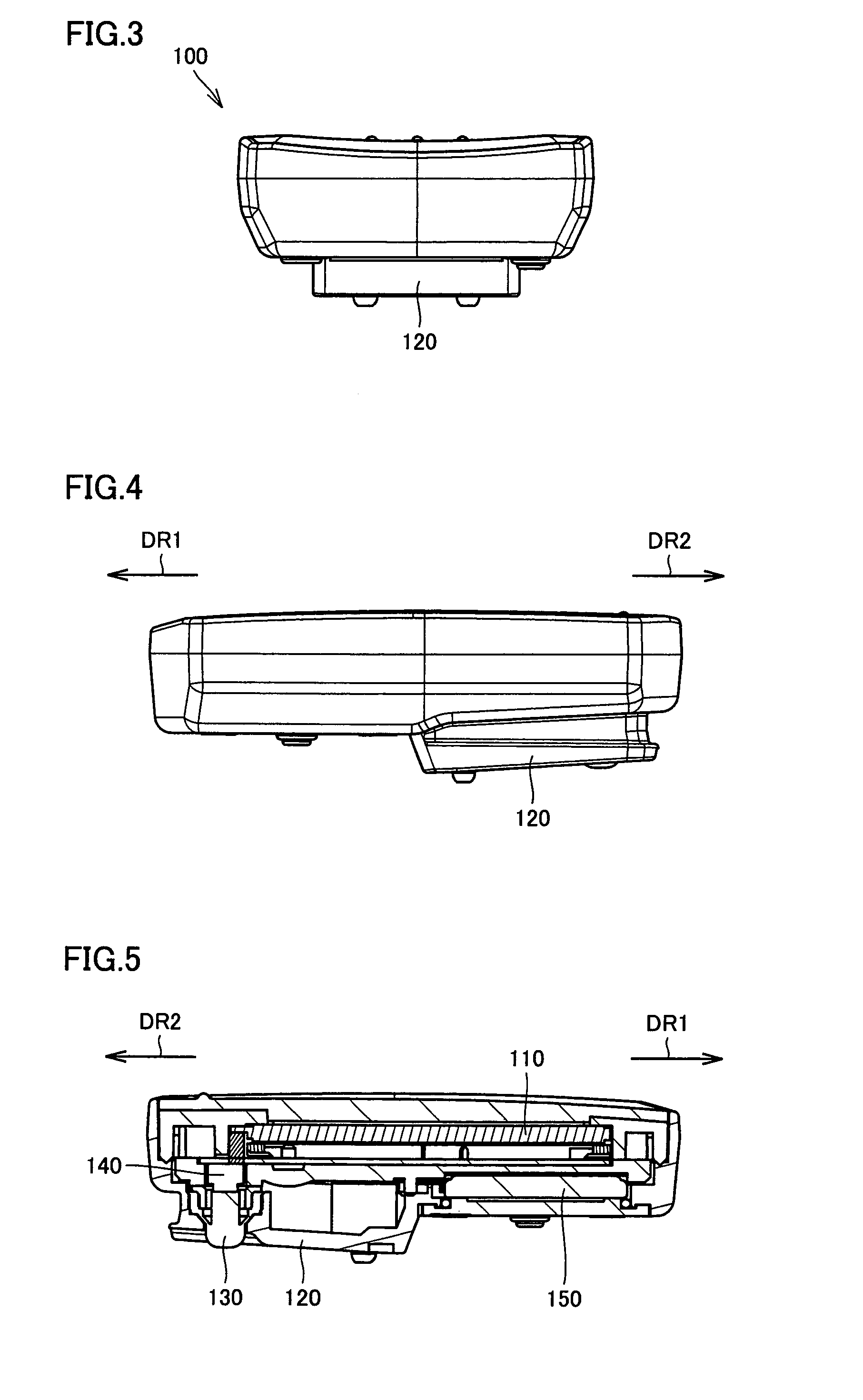
[0031]Referring to FIGS. 1 to 5, a body 100 according to this embodiment includes a display part 110 displaying various data, an engaging part 120 engaging with a securing tool, a rubber button 130 which is so provided as to protrude from the bottom surface of body 100, a tact switch 140 provided on rubber button 130 and a battery 150.

[0032]Body 100 is attached to a handlebar, frame or stem of a bicycle, for example. Referring to FIGS. 1, 4 and 5, arrows DR1 and DR2 correspond to the front and rear sides of the bicycle respectively. Display part 110 displays a plurality of data such as the traveling speed, the traveling time, the travel distance, the time of day, the average speed and the maximum speed of the bicycle, for example. Display part 110 does not simultaneousl...


PUM


Abstract

A display unit, attached to a bar forming a handlebar, frame or stem of a bicycle with a securing tool, comprises a body having a display part capable of realizing a first display state displaying first data (traveling speed, for example) and a second state displaying second data (traveling distance, for example). The first and second display states are switched by pressing down body from above.

Description

BACKGROUND OF THE INVENTION[0001]1. Field of the Invention[0002]The present invention relates to a display unit, and more particularly, it relates to a display unit capable of switching a plurality of display states.[0003]2. Description of the Background Art[0004]A display unit, attached to a bar, capable of displaying various data is known in general.[0005]For example, Japanese Patent Laying-Open No. 2005-350064 discloses a display unit for a bicycle comprising a bracket attachable to the frame of the bicycle, a display part and a control part. The control part changes at least one of the three attributes of color, i.e. the hue, the chroma and the brightness of the backlight in response to received data.[0006]A display unit displaying a plurality of different data on a display part thereof may display only part of the data on the display part and switch the display state for displaying the remaining data, in order to effectively utilize the limited area of the display part. Such a ...

Claims


Application Information

Patent Timeline
Patent Type & Authority Patents(United States)
IPC IPC(8): H01H9/00B62J99/00
CPCB62J11/00B62J99/00B62J2099/0026B62J2099/0033B62J50/225B62J50/22B62J43/30
Inventor UEDA, TAKASHIOKAMOTO, TAKAHIRO
Owner CATEYE
Why Eureka
Try Eureka