Anti-rebound locking device for the deployable fin of a projectile

a technology of anti-rebound and locking device, which is applied in the direction of self-propelled projectiles, projectiles, weapons, etc., can solve the problems of rebounding of the fin, aerodynamic imbalance, and impair flight accuracy, and achieve the effect of simple reliabl

Active Publication Date: 2011-04-05
NEXTER MUNITIONS
View PDF9 Cites 1 Cited by
  • Summary
  • Abstract
  • Description
  • Claims
  • Application Information

AI Technical Summary

Benefits of technology

[0014]The aim of the invention is to propose a simple reliable device which avoids rebounding of the fins and which also ensures their locking at the end of their moving into position.
[0015]Because of the principle of its functioning, the effectiveness and reliability of the device are all the greater in that the kinetic energy of the fin is high and in particular the opening speed.
[0016]The device, moreover, in no way hinders the deployment movement itself which ensures the final positioning of the fin and namely eliminates the risk (encountered with certain known devices) of stopping the fin before its deployment is fully completed.

Problems solved by technology

However, rapid deployment may well lead to the fin rebounding and there is, a priori, a certain contradiction between the requirement for the fins to be rapidly opened (a few milliseconds) and that of ensuring the reliable locking without rebound of the fins.
Moreover, the different positions of the fins constituting the tail piece cause aerodynamic imbalances which are both undesirable and impair flight accuracy.
We note that, for the case of canards, failure to lock is catastrophic.
The solutions associating bolts and notches are not satisfactory since there is always functional play remaining which enables angular movement of the fin with respect to its support.
This results in movements or vibrations of the fins which impair firing accuracy.
To this day, there are no satisfactory solutions to prevent rebounding.

Method used


Image

  • Anti-rebound locking device for the deployable fin of a projectile
  • Anti-rebound locking device for the deployable fin of a projectile
  • Anti-rebound locking device for the deployable fin of a projectile

Examples


Embodiment Construction

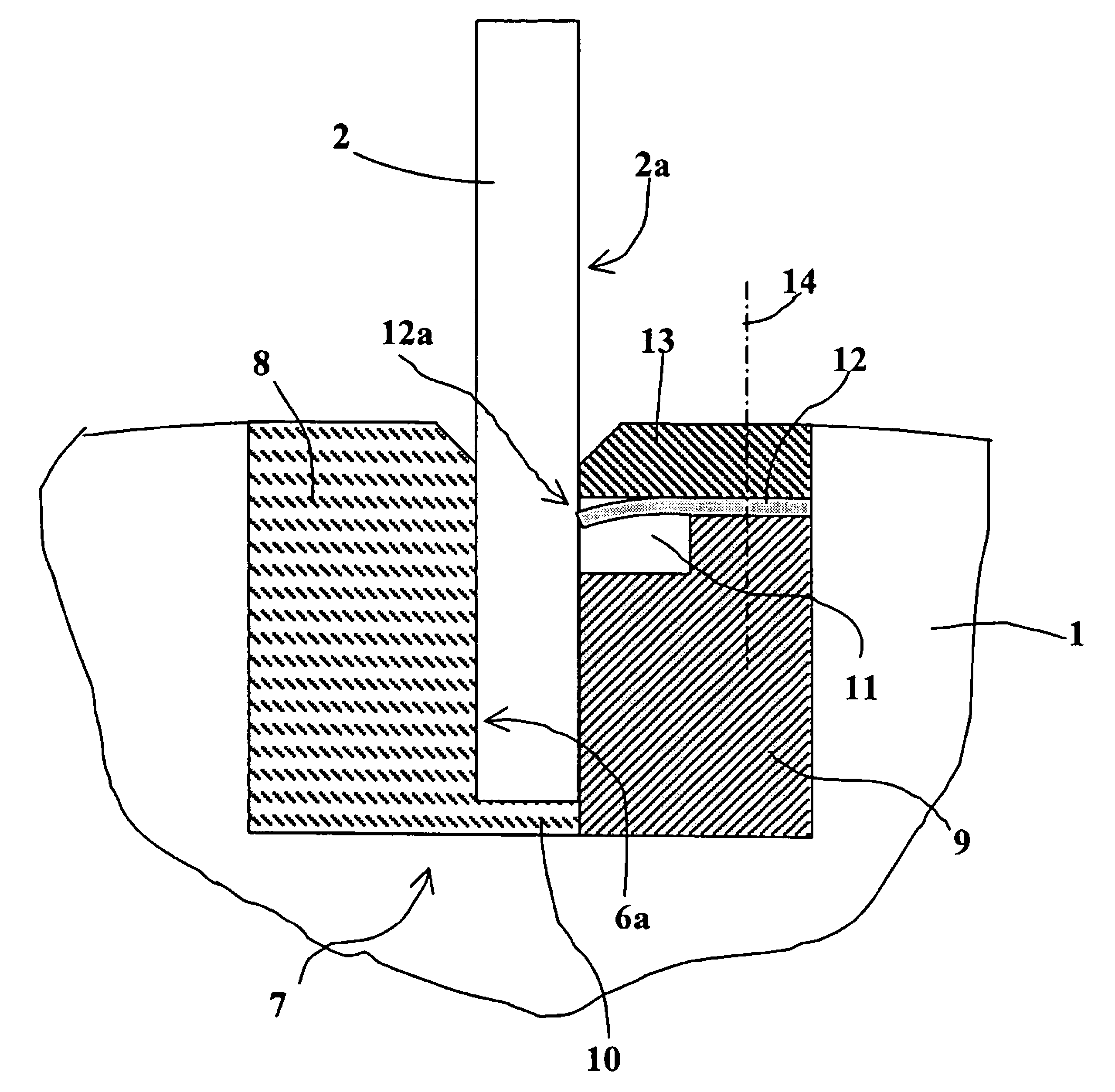
[0027]With reference to FIG. 1, a projectile 1 incorporates several deployable fins 2 at its rear part, only one of which is shown here.

[0028]The fin is in the folded position, pressing against and along the projectile body 1 and oriented substantially along axis 3 of the projectile. During firing, it pivots, thanks to a deployment mechanism 4, which is not described further here since it is not the subject of the present invention.

[0029]This deployment mechanism may be analogous to that described in patent FR-2860577 to which reference may be made for further details.

[0030]When the fin is deployed, a rear part 5 of the fin penetrates into a radial groove 6 arranged on a support 7 integral with the projectile body 1.

[0031]The support 7 may be more clearly seen in FIG. 2.

[0032]The support 7 comprises two elements 8 and 9 which are arranged on either side of the groove 6. These elements will be made integral with the projectile body 1, for example by screws (not shown).

[0033]One of th...


PUM


Abstract

The invention relates to a locking device for a deployable surface or fin of a projectile characterized in that it incorporates at least one flexible tongue, one end of which protrudes in the groove, a recess to the side of the groove enabling the tongue to bend in a first direction to enable the fin to enter the groove.

Description

BACKGROUND OF THE INVENTION[0001]1. Field of the Invention[0002]The technical scope of the invention is that of locking devices for the deployable surfaces of projectiles, such as wings, elevons or fins.[0003]2. Description of the Related Art[0004]It is classical to provide projectiles with stabilizing fins fired from a smooth-bore gun. During firing such fins lie along an external surface of the projectile or are inserted into radial housings. They deploy upon exiting the barrel to ensure their stabilizing function.[0005]The stabilizing elements are generally sought to be deployed as quickly as possible to reduce the projectile's time of unstable flight, which is a source of dispersion with respect to the expected trajectory.[0006]Patent FR-2860577 thus describes a deployment device for such fins.[0007]Once deployed, the fins must occupy a reliable position and remain in this position. The absence of rebound is furthermore sought after since the existence of rebound delays the time...

Claims


Application Information

Patent Timeline
Patent Type & Authority Patents(United States)
IPC IPC(8): F42B15/01
CPCF42B10/16F42B10/14
Inventor TROUILLOT, CHRISTIAN
Owner NEXTER MUNITIONS
Why Eureka
Try Eureka