
Threadless torque connector

a technology of threadless torque and connector, which is applied in the direction of drilling rods, drilling casings, drilling pipes, etc., can solve the problems of thread wear, untorque, and untorque, and achieve the effect of safe release of sub-ensembles from each other and simple yet reliabl

Inactive Publication Date: 2016-10-04
UNMANNED AD HOC IND INC
View PDF23 Cites 2 Cited by
  • Summary
  • Abstract
  • Description
  • Claims
  • Application Information

AI Technical Summary

Benefits of technology

The solution provides a reliable, threadless connection system that ensures secure assembly and disassembly without tools, reducing the risk of mechanical failures and injuries, and enabling efficient drilling and milling operations by preventing thread-related issues.

Problems solved by technology

Thread fatigue can result in mechanical failure of the threads, thread wear, thread back-off, un-torque, tools lost in hole and required fishing operations to retrieve out of the well.
It has also resulted in injury, as when a thread is not made up properly, specifications are not adhered to, human error, surface handing equipment failure, falling objects, etc.

Method used


Image

  • Threadless torque connector
  • Threadless torque connector
  • Threadless torque connector

Examples


Embodiment Construction

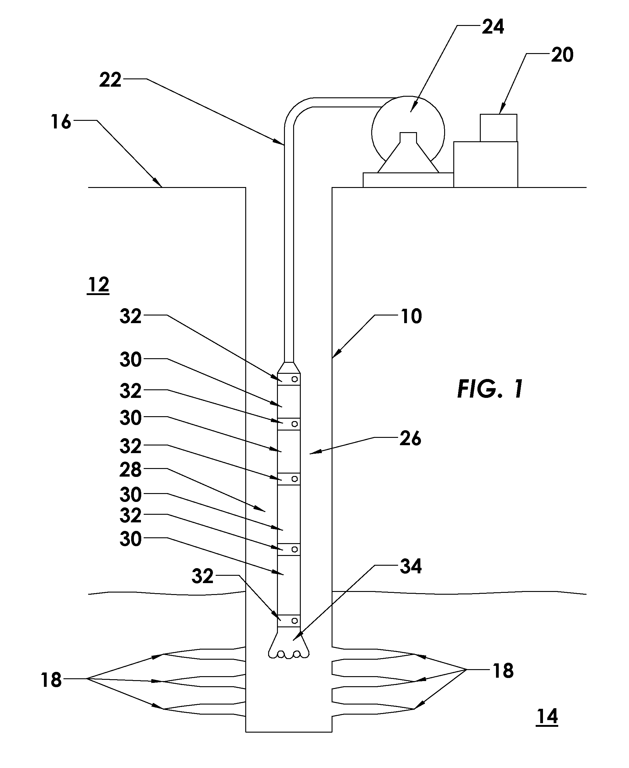
[0018]FIG. 1 illustrates an exemplary wellbore 10 which has been drilled through the earth 12 down to a hydrocarbon-bearing formation 14 from the surface 16. Perforations 18, of a type known in the art, extend from the wellbore 10 and outwardly into the formation 14 to permit hydrocarbon production fluid to flow from the formation 14 to the interior of the wellbore 10.

[0019]A coiled tubing injection unit 20, of a type known in the art, is located at the surface 16 and is depicted injecting a coiled tubing production string 22 from spool 24 into the wellbore 10. At the distal end of the coiled tubing string 22 is affixed a bottom hole assembly (BHA) also known as a motor head assembly (MHA) 26. An annulus 28 is defined between the bottom hole assembly 26 and the wellbore 10. It is noted that, while a coiled tubing arrangement is depicted, the devices and methods of the present invention are not limited to use within a coiled tubing system. The invention may also be used with conventi...


PUM


Abstract

A threadless connection assembly for use in connecting two tubular members. A connection assembly includes connection portions having interlocking splines and a link lock that secures the two connection portions axially.

Description

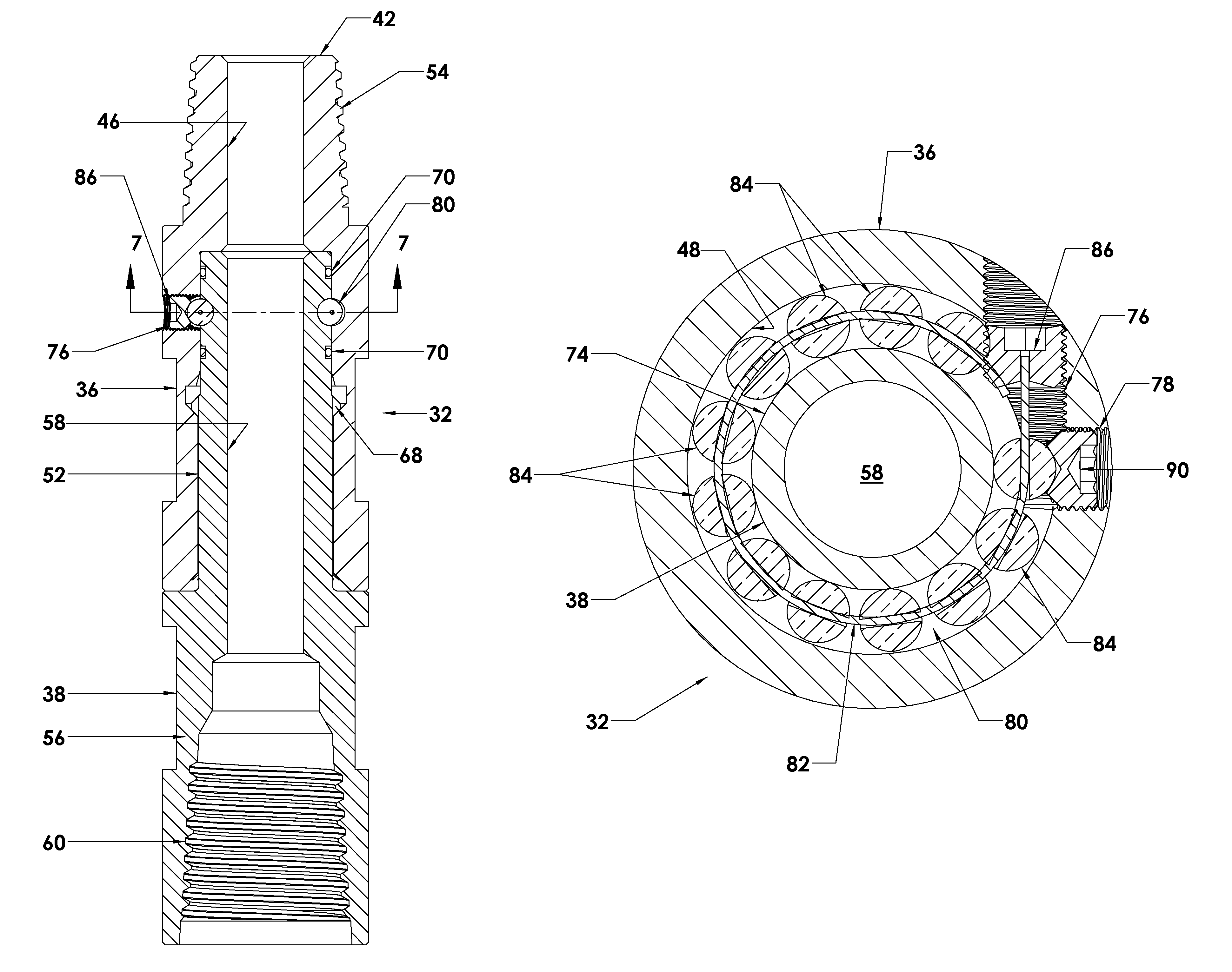
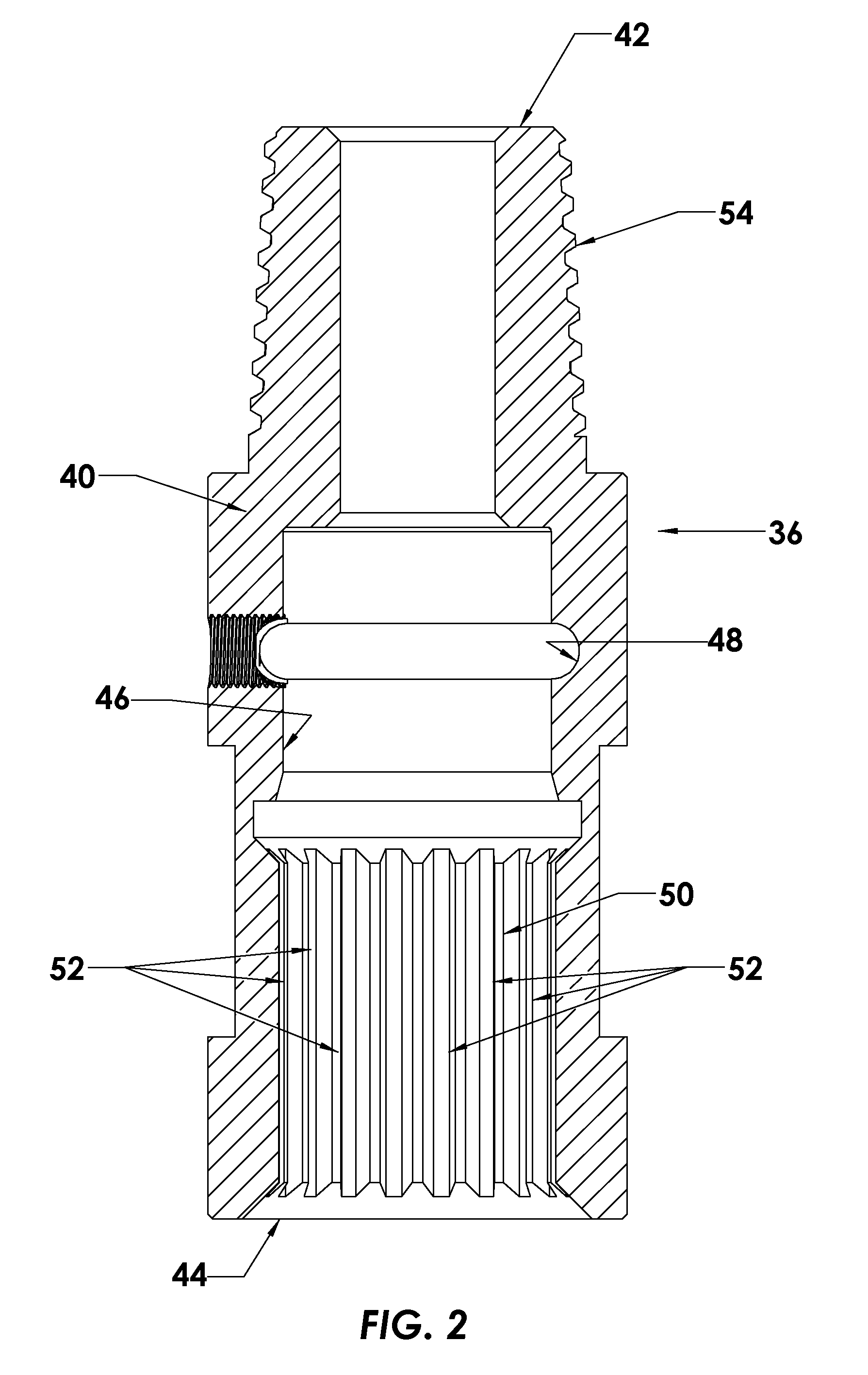
BACKGROUND OF THE INVENTION[0001]1. Field of the Invention[0002]The present invention generally relates to the design of a mechanical assembly used in conjunction with coiled tubing and drilling tubulars for downhole operations. In particular aspects, the invention relates to devices used for connecting bottom hole assemblies together to the end of the coiled tubing or jointed pipe without the need for threaded connections, hand tools, hydraulic or mechanical make up devices, etc. It permits an end user to perform drilling and milling operations without the risk of the connection backing off, unscrewing and negates the risk of leaving the bottom hole assembly downhole. The system has two primary functions; A. at surface to eliminate the use of make-up tongs, torque wrenches, come-a-longs, load cells, or the use of hand tools to tighten the BHA together. Because there are no threads throughout the entire system therefore safety incidents such as dropped objects, injuries from hand to...

Claims


Application Information

Patent Timeline
Patent Type & Authority Patents(United States)
IPC IPC(8): F16L37/14E21B17/046E21B17/20
CPCE21B17/046E21B17/20F16L37/148E21B17/0465
Inventor MCLAUGHLIN, STUARTDAHSE, ROXANNE R.KOLAR, RAYMONDRAMIREZ, JEREMYGRIFFIN, CAMERONKATEN, DAN
Owner UNMANNED AD HOC IND INC
Learn More