Revolving radiation collimator

a radiation collimator and rotating technology, applied in the field of rotating radiation collimators, can solve the problems of prone to mechanical failure, complex mechanism, bulky, etc., and achieve the effects of rapid and automatic switching, low cost, and rapid chang

Active Publication Date: 2021-07-13
ZAP SURGICAL SYST INC
View PDF45 Cites 1 Cited by
  • Summary
  • Abstract
  • Description
  • Claims
  • Application Information

AI Technical Summary

Benefits of technology

[0007]In another aspect, the collimator body is motorized and precisely indexed for rapid and exacting computer-controlled positioning of the selected collimator channel geometry with the radiation source, thereby delivering a desired beam shape to the precise dimensions required at the target. By using a revolving collimator wheel, multiple sizes of the beam may be utilized during one treatment, quickly and automatically switching between two or more selected collimators.
[0008]These collimation assemblies have the advantage of being rapidly changeable by computer control, while remaining small, reliable in their simplicity and low in cost. Moreover, such assemblies can utilize a single motor to switch between select one or more collimator channels. The aspects of the invention described herein allow for a more reliable radiation collimator that can quickly and precisely change X-ray exposure from 1 mm to 30 mm diameter at isocenter, and can function more reliably than many prior art collimators. Such collimator assemblies enable rapid, automated (motorized and computer controlled) changing of beam aperture in the service of therapeutic radiation delivery, for example to treat brain tumors.
[0009]The collimator systems described herein allow for beam collimation without requiring use of a conventional block collimator and / or multi-leaf collimator system, such as those commonly used in conventional radiation treatment systems, which are bulky and prone to mechanical malfunction over time.
[0013]In another aspect, the treatment system includes a collimator shield. The collimator shield can be configured to surround at least a portion of the collimator body during delivery of therapy so as to block radiation from non-aligned collimator channels while allowing passage of a therapy beam from the selected, aligned collimator channel. In some embodiments, the collimator shield substantially surrounds a portion of the collimator wheel facing the radiation source except for the entry orifice of the selected, aligned collimator channel. In some embodiments, the collimator shield substantially surrounds the collimator body except for an aperture at an apex of the shield through which includes the exit orifice of the selected aligned collimator channel is exposed as well as a passage at the inlet orifice of the aligned channel to allow entry of the radiation beam through the selected channel. While a conically shaped shield is depicted in the embodiments presented herein, it is appreciated that the collimator shield could be formed in various different shapes so long as the shield allows radiation to pass through the selected, aligned channel while blocking radiation emitted from non-selected channels and from around the shield itself, resulting in minimal radiation leakage around the intended beam.

Problems solved by technology

This complex mechanism is complex, bulky, expensive, and prone to mechanical failure.

Method used


Image

  • Revolving radiation collimator
  • Revolving radiation collimator
  • Revolving radiation collimator

Examples


Embodiment Construction

[0023]The invention relates generally to radiation treatment systems and methods of use, in particular collimator systems provide selective control and delivery of collimated beams of radiation.

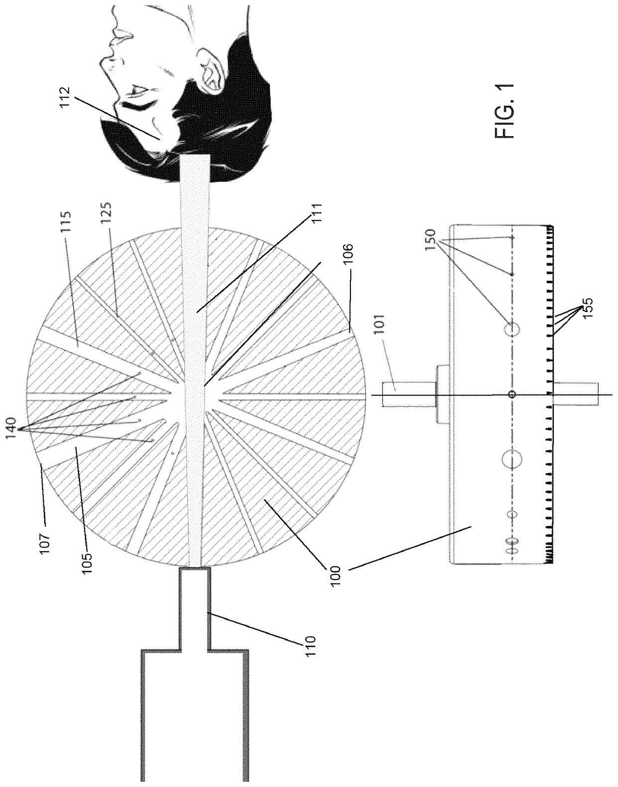
[0024]FIG. 1 shows a cross sectional view of a revolving collimator wheel 100 having collimator channels 140 passing therethrough. Collimator wheel 100 has longitudinally extending channels or collimator channels 105, 115 and 125 defined therein, for example machined through the body of collimator wheel 100. The figure shows multiple other channels that are not labeled for the sake of clarity of the drawing. The collimator channels may be of various sizes, diameters or shapes. In some embodiments, each collimator channel is of a different diameter. For example, as shown in FIG. 1, collimator channel 105 is of larger bore than collimator channel 115, which is of larger bore than collimator channel 125. Each collimator channel extends from a radiation entrance aperture 106 to an exit aperture 1...


PUM


Abstract

Devices, systems and method that allow for delivery of therapeutic radiation beams of differing sizes or shapes during a radiation treatment are provided herein. Such devices can include a rotatable collimator body having multiple collimator channels of differing size or shape defined therein, the channels extending through the collimator body substantially perpendicular to the axis of rotation. The collimator body can include markers thereon to facilitate detection of an alignment position by a sensor of a control system to allow the collimator body to be rapidly and accurately moved between alignment positions to facilitate delivery of differing therapy beams during a treatment.

Description

CROSS-REFERENCES TO RELATED APPLICATIONS[0001]The present application claims the benefit of priority of U.S. Provisional Application No. 62 / 502,472 filed May 5, 2017 and PCT Application Serial No. PCT / US2017 / 038256 filed Jun. 20, 2017, the entire contents of which are incorporated herein by reference.[0002]The present application is related to PCT Application Serial No. PCT / US / 2017 / 054880 filed Oct. 3, 2017, which is assigned to the same assignee as the present application and incorporated by reference herein in its entirety for all purposes.BACKGROUND[0003]The overarching goal of the collimator system is to deliver a beam of radiation produced by a source (for example a LINAC) to a target (for example a tumor in a patient's brain). Because it is desirable to irradiate a tumor, but generally not desirable to irradiate surrounding healthy tissue, the size and the shape of each beam is of critical importance. In order to control the shape (for example diameter or 2D cross sectional ar...

Claims


Application Information

Patent Timeline
Patent Type & Authority Patents(United States)
IPC IPC(8): A61N5/10G21K1/02G21K1/04G01B11/27
CPCA61N5/1042A61N5/1081G01B11/27G21K1/025G21K1/046A61N2005/1095
Inventor WILBUR, RAYMONDACHKIRE, YOUNESBIRANG, MANOOCHER
Owner ZAP SURGICAL SYST INC
Why Eureka
Try Eureka