
System and method for jerk limited trajectory planning for a path planner

a path planner and trajectory planning technology, applied in the direction of electric programme control, program control, instruments, etc., can solve the problems of complex calculations that are not readily adaptable to real time implementations, and do not yield closed forms

Active Publication Date: 2011-04-05
INTELLIGENT PLATFORMS LLC
View PDF22 Cites 63 Cited by
  • Summary
  • Abstract
  • Description
  • Claims
  • Application Information

AI Technical Summary

Benefits of technology

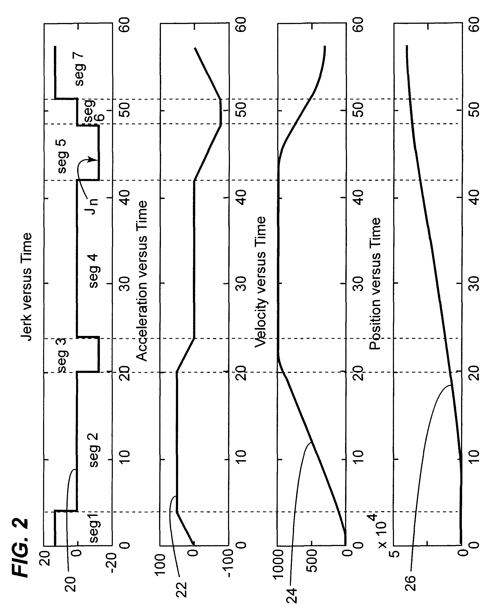
[0011]In another embodiment of the invention, a method for generating a motion profile in real time comprises breaking a move into a first phase and a second phase. The method further comprises commanding the move toward a constant velocity segment during the first phase, and monitoring the first phase to determine when during a move in progress it is necessary to implement a jerk value required to successfully reach end conditions.

Problems solved by technology

This method does result in a solution, but it requires complex calculations that are not readily adaptable to real time implementations.
Furthermore, in many cases, a complex solution results that does not yield a closed form.

Method used


Image

  • System and method for jerk limited trajectory planning for a path planner
  • System and method for jerk limited trajectory planning for a path planner
  • System and method for jerk limited trajectory planning for a path planner

Examples


Embodiment Construction

[0021]An embodiment of the present invention concerns a system and method for generating a time based motion profile that can be solved in real time and also satisfies the initial and final conditions while not exceeding programmed limit values. Limit values may be minimum or maximum values or a combination thereof.

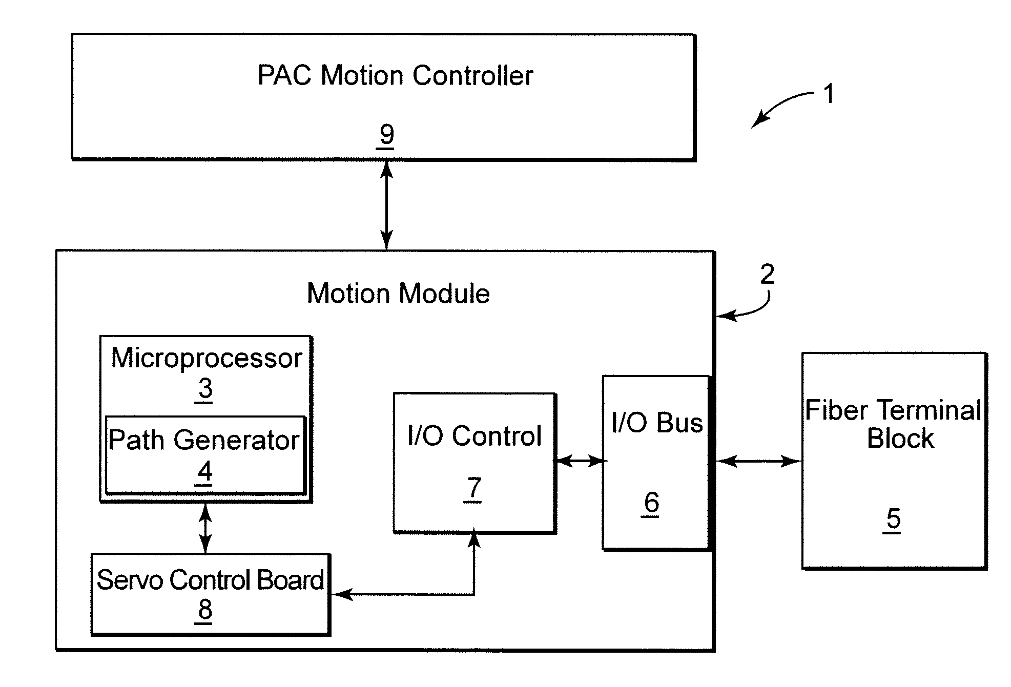
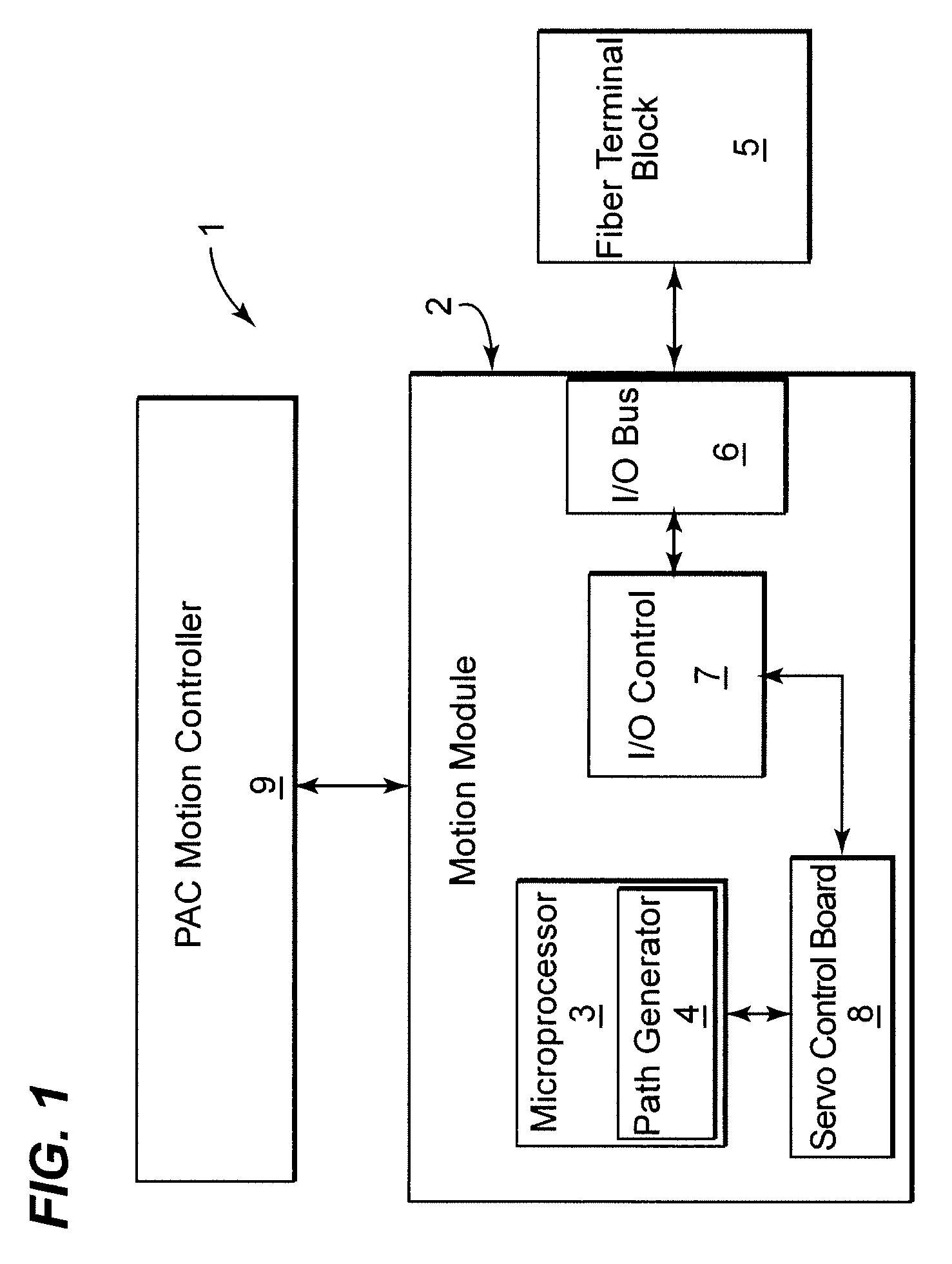
[0022]Referring now to FIG. 1, a block diagram of a Programmable Automation Controller (PAC) type motion system 1 for path planning is shown according to one embodiment of the present invention. PAC system 1 includes a PAC system type motion controller 9, PAC system type motion module (PMM) fiber terminal block 5 and (PMM) motherboard 2 comprising microprocessor subsystem 3. A processor system can also be used. PMM motherboard 2 further includes several subsystems including path generator 4. Path generator 4 is a firmware subsystem that runs on microprocessor 3 that is dedicated to path planning. Other firmware subsystems that support the functions of PMM motherboard 2 in...


PUM


Abstract

A system for generating a motion profile in real time includes a processor. The processor breaks a move into a first phase and a second phase. The first phase includes commanding the move toward a constant velocity segment, and the second phase includes monitoring the first phase to determine when during a move in progress it is necessary to implement a jerk value required to successfully reach end conditions. The processor also transmits command signals based upon the motion profile and calculates the point at which the second phase must take control of the move in progress to reach a target position. The system further includes at least one input / output module that receives command signals. A method for generating a motion profile in real time is also presented.

Description

BACKGROUND OF THE INVENTION[0001]1. Field of the Invention[0002]The subject matter described herein relates generally to automated motion controllers and, more particularly, to jerk limited trajectory planning.[0003]2. Related Art[0004]Path planners or path generators typically comprise motion controllers. Path planners are used to control mechanical devices requiring motion and determine the movements of controlled elements in the mechanical devices. Mechanical devices that employ path planning can be found in various industrial systems such as manufacturing, assembling, packaging and other capacities. Servomotors, for example, are one such type of device. Other motors may control the movements of elements such as drill bits or robotic arms.[0005]Path generators use various kinetic path algorithms along with discrete time controllers to provide path profiles. The path profiles are based on specified motion parameters. The specified motion parameters may include the following comman...

Claims


Application Information

Patent Timeline
Patent Type & Authority Patents(United States)
IPC IPC(8): G05B19/19
CPCG05B19/416G05B19/19G05B2219/41408G05B2219/43168Y10S388/904
Inventor MILLER, DANIEL H.MORRISON, WILLIAM LINDSAY
Owner INTELLIGENT PLATFORMS LLC
Learn More