Supercharge Your Innovation With Domain-Expert AI Agents!

Noise quantity measuring apparatus

a technology of noise quantity and measuring apparatus, applied in the field of noise quantity measuring apparatus, can solve the problem that the noise quantity measuring apparatus cannot adapt to the input video of the video camera

Inactive Publication Date: 2011-04-05
LAPIS SEMICON CO LTD
View PDF4 Cites 0 Cited by
  • Summary
  • Abstract
  • Description
  • Claims
  • Application Information

AI Technical Summary

Benefits of technology

Enables accurate detection of noise in low-luminance video portions even when automatic gain control is applied, preventing misinterpretation of luminance changes and ensuring comprehensive noise measurement.

Problems solved by technology

However, a problem arises in that the noise quantity measuring apparatus cannot adapt to input video of a video camera or the like having an automatic gain control function.

Method used


Image

  • Noise quantity measuring apparatus
  • Noise quantity measuring apparatus
  • Noise quantity measuring apparatus

Examples


first preferred embodiment

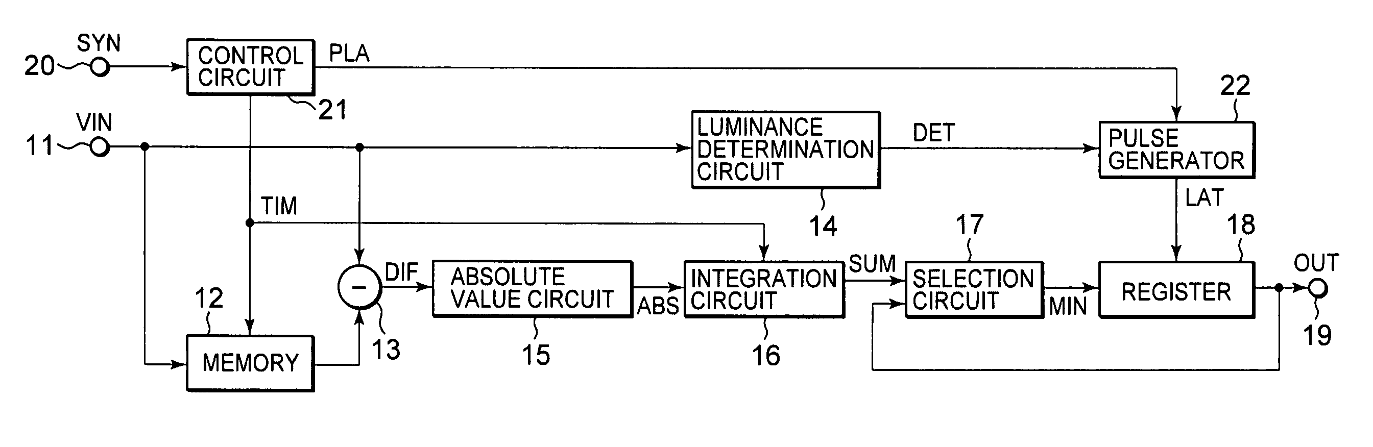
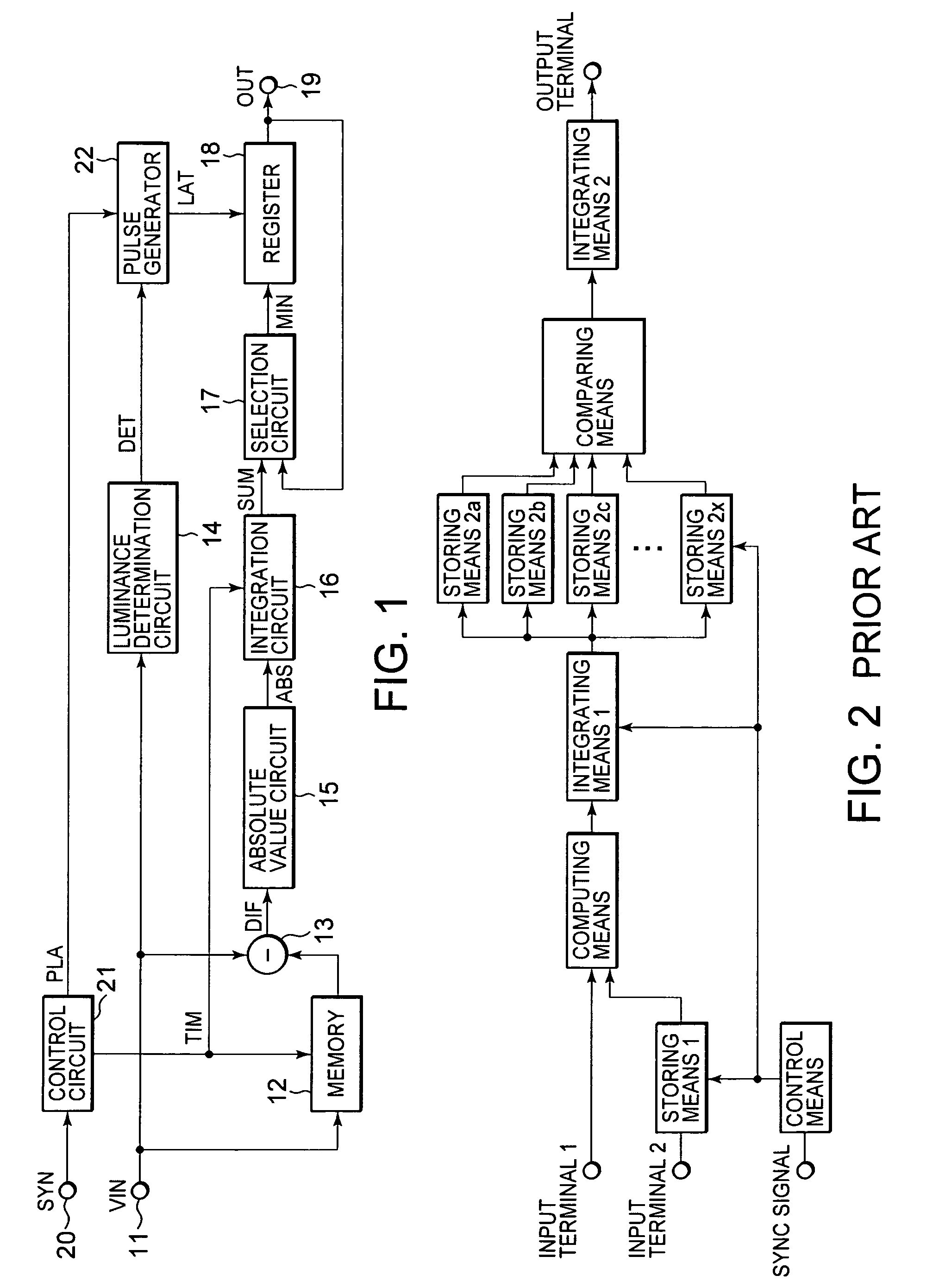
[0027]FIG. 1 is a configuration diagram showing a noise quantity measuring apparatus according to a first embodiment of the present invention.

[0028]The noise quantity measuring apparatus measures the quantity of noise in a vide input signal VIN inputted from an input terminal 11 and includes a memory 12, a subtraction circuit 13 and a luminance determination circuit 14, which are respectively supplied with the video input signal VIN. The memory 12 has a memory or storage capacity that stores the video input signal VIN corresponding to at least one frame therein, and outputs the stored video input signal VIN with being delayed by at least one frame. The subtraction circuit 13 calculates each luminance level difference DIF developed every pixel between a video input signal VIN newly inputted from the input terminal 11 and the video signal delayed by at least one frame by the memory 12. The luminance determination circuit 14 outputs a detection signal DET when the video input signal VI...

second preferred embodiment

[0040]FIG. 5 is a configuration diagram showing a noise quantity measuring apparatus according to a second embodiment of the present invention. Constituent elements common to those shown in FIG. 1 are respectively given common reference numerals.

[0041]The noise quantity measuring apparatus is configured in such a manner that the pulse generator 22 shown in FIG. 1 is omitted, and that a control circuit 21 applies a prelatch signal PLA outputted therefrom to a register 18 as a latch signal LAT as it is, and a mask circuit 23 is provided between an integration circuit 16 and a selection circuit 17 and controlled by a detection signal DET outputted from a luminance determination circuit 14. When the detection signal DET is supplied to the mask circuit 23, the mask circuit 23 outputs a maximum value (e.g., 255 if a 8-bit integration circuit is taken) outputtable from the integration circuit 16 regardless of each value outputted from the integration circuit 16. Incidentally, when the dete...


PUM

PropertyMeasurementUnit
noise quantityaaaaaaaaaa
luminanceaaaaaaaaaa
luminance levelaaaaaaaaaa

Abstract

The present invention provides a noise quantity measuring apparatus adaptable to a video input signal subjected to automatic gain control. A luminance determination circuit compares luminance levels of respective pixels constituting a video input signal VIN and a predetermined threshold value for every arbitrary area Ai. If even one of the luminance levels exceeds the threshold value, then the luminance determination circuit outputs a detection signal DET to the corresponding area Ai. Sums SUMi of luminance level differences developed every plural arbitrary areas Ai, which are outputted from an integration circuit, are supplied to a selection circuit, where they are compared with an output signal OUT. Thereafter, each smaller value is supplied to a register. The register holds the output of the selection circuit in accordance with a latch signal LAT supplied from a pulse generator. On the other hand, when the detection signal DET is outputted, the latch signal LAT outputted from the pulse generator is stopped. Thus, the sum of the luminance level differences with respect to each area having pixels whose luminance levels exceed the threshold value, is ignored and eliminated from an output signal OUT indicative of the quantity of noise.

Description

BACKGROUND OF THE INVENTION[0001]The present invention relates to a technique for measuring the quantity of noise contained in a video signal.[0002]FIG. 2 is a configuration diagram of a conventional noise quantity measuring apparatus described in a patent document 1 (Japanese Unexamined Patent Publication No. 2005-229166).[0003]The noise quantity measuring apparatus extracts, for example, an area A of 10×10 pixels from a first video signal inputted from an input terminal 1 and extracts, for example, an area B of 5×5 pixels corresponding to a set of adjacent pixels with an arbitrary pixel lying in the area A as the center, as a basic image. On the other hand, the first video signal is supplied even to an input terminal 2. The first video signal applied to the input terminal 2 is stored in a storing or memory means 1 and read as a second video signal. Thus, the second video signal assumes a video signal lying immediately before at least one frame from the first video signal.[0004]A c...

Claims


Application Information

Patent Timeline
Patent Type & Authority Patents(United States)
IPC IPC(8): G06K9/00H04N5/21H04N17/00
CPCH04N17/00A01G2/00E01C5/00E01C5/18E01C5/20E01C15/00E01C2201/10
Inventor SATOU, TAKAYUKITAKAHASHI, HIDETSUGU
Owner LAPIS SEMICON CO LTD
Features
  • R&D
  • Intellectual Property
  • Life Sciences
  • Materials
  • Tech Scout
  • Unparalleled Data Quality
  • Higher Quality Content
  • 60% Fewer Hallucinations
Learn More