
Thrust bearing for a gyratory crusher and method of supporting a vertical shaft in such a crusher

a technology of gyratory crusher and bearing, which is applied in the direction of bearings, shafts and bearings, rotary bearings, etc., can solve the problems of limited withstandability of the crusher, and achieve the effects of reducing mechanical wear and power losses, reducing maintenance costs, and reducing the wear of bearing plates and power losses

Inactive Publication Date: 2011-04-12
SANDVIK INTELLECTUAL PROPERTY AB
View PDF9 Cites 10 Cited by
  • Summary
  • Abstract
  • Description
  • Claims
  • Application Information

AI Technical Summary

Benefits of technology

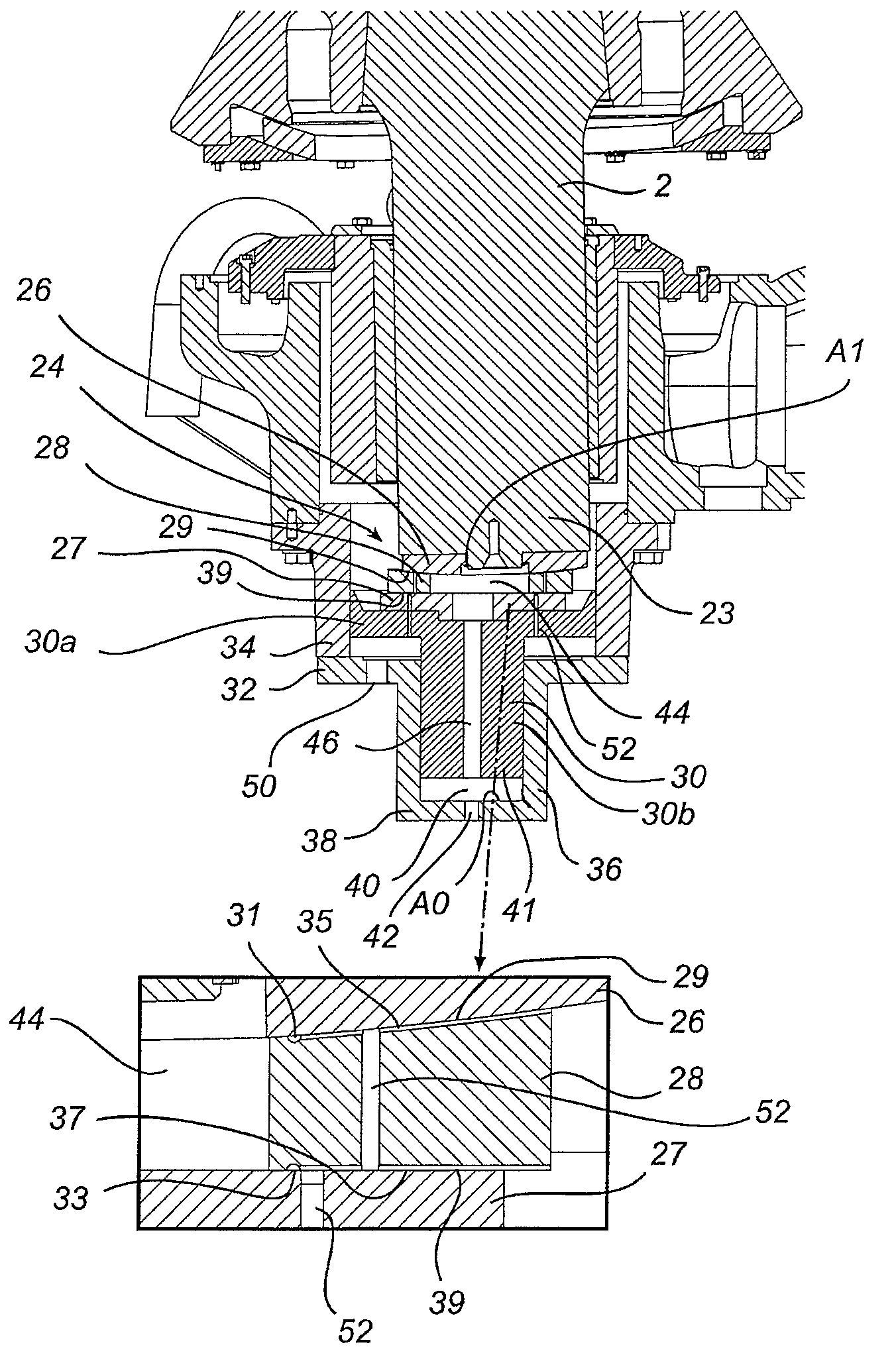
[0011]An advantage of this gyratory crusher is that the mechanical wear that occurs when the bearing plates slide against one another during operation of the crusher is considerably reduced by the load on the thrust bearing being relieved in the vertical direction. This substantially reduces the cost of maintaining the crusher. A further advantage is that the large power losses incurred as a result of the bearing plates rubbing against one another generating frictional heat can be significantly reduced by the load on the thrust bearing being relieved. A gyratory crusher is thus provided which in operation consumes less energy than previously known crushers. Previously, the mean crushing force of the crusher, for example, the load in the form of feed material to be crushed, that the crusher can withstand has been limited by the strength of the bearing plates and by the heat generation in the sliding surfaces of the thrust bearing. By relieving the load on the bearing plates it is thus possible to increase the mean crushing force of the crusher and / or its capacity, since the crusher is able to withstand higher loads with maintained strength as regards the bearing plates.
[0021]According to one embodiment, the liquid pressure in the second space is maintained at substantially the same level as the liquid pressure in the first space. An advantage of this embodiment is that a predictable upward force will act on the vertical shaft, which means that a desired relieving of the load on the thrust bearing is achieved, without the risk of play occurring in the thrust bearing. As the pressure is substantially the same in the first and second spaces, it is only the proportion between the respective horizontal pressure areas on which the pressure is acting that determines how much of the vertical forces pass through the thrust bearings and how much pass through the first and second spaces.

Problems solved by technology

Previously, the mean crushing force of the crusher, for example, the load in the form of feed material to be crushed, that the crusher can withstand has been limited by the strength of the bearing plates and by the heat generation in the sliding surfaces of the thrust bearing.

Method used


Image

  • Thrust bearing for a gyratory crusher and method of supporting a vertical shaft in such a crusher
  • Thrust bearing for a gyratory crusher and method of supporting a vertical shaft in such a crusher
  • Thrust bearing for a gyratory crusher and method of supporting a vertical shaft in such a crusher

Examples


first embodiment

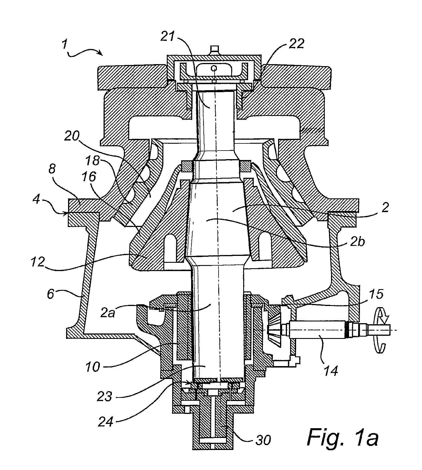
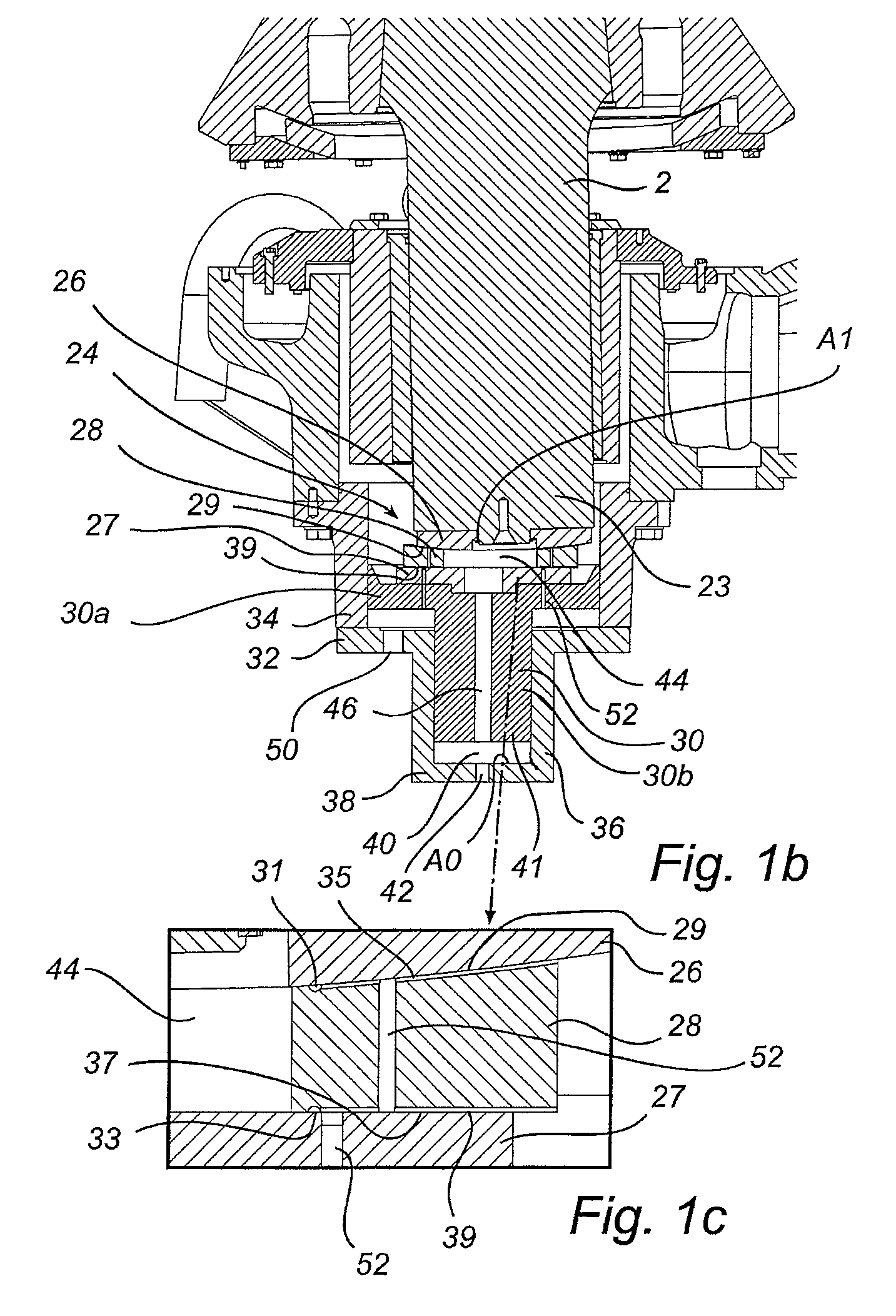
[0031]FIG. 1a illustrates schematically a gyratory crusher 1 according to a The gyratory crusher 1 has a vertical shaft 2 and a frame 4 including a frame bottom part 6 and a frame top part 8. An eccentric device in the form of an eccentric 10 is rotatably arranged about the lower portion 2a of the shaft 2. A crushing head 12 is fixedly mounted on an upper portion 2b of the shaft 2. A drive shaft 14 is arranged to rotate the eccentric 10 by means of a motor (not shown) and a gear rim 15 mounted on the eccentric 10. The vertical shaft 2 is carried at its upper end 21 in a top bearing 22 in the frame top part 8. When the drive shaft 14 rotates the eccentric 10, during operation of the crusher 1, the shaft 2 and the crushing head 12 mounted thereon will execute a gyrating movement.

[0032]A first crushing shell 16 is fixedly mounted on the crushing head 12. A second crushing shell 18 is fixedly mounted on the frame top part 8. A crushing gap 20 is formed between the two crushing shells 1...

second embodiment

[0061]Thus, the upper sliding surface 229 of the thrust bearing 224 has the same function as the upper sliding surface 129 of the second embodiment described above, for example, it serves as a hydrostatic bearing, which through the supply of oil at high pressure forms a load-bearing oil film in the upper sliding surface 229 of the thrust bearing 224. As a result the wear of the first bearing plate 226 and the third bearing plate 228 as well as the power losses are significantly reduced. The thickness of the oil gap formed in the upper sliding surface 229 is determined by the flow out from the thrust bearing 224, which in turn is determined by the constriction 266.

[0062]The lower sliding surface 239 of the thrust bearing 224 works in the same way as the lower sliding surface 39 of the embodiment described in FIGS. 1a-c. For the same reasons as those described previously with reference to FIG. 1c, a circular drain groove 231 and radial drain grooves 235 have been provided in the lower...


PUM


Abstract

A gyratory crusher includes a crushing head on which a first crushing shell is mounted, and a frame on which a second crushing shell is mounted. The crusher has a thrust bearing which is made up of horizontal bearing plates and which is located between a vertical shaft and a piston arranged vertically below the vertical shaft. The crusher further has a first space, which is adapted to receive a variable amount of pressurized liquid, the first space being defined by the piston and a piston housing formed in the frame, and a second space which is adapted to receive, by way of a duct, pressurized liquid from the first space, the second space being located between the vertical shaft and the piston and at least partly accommodated in an opening in at least one of the bearing plates. The first space and the second space are adapted, by the liquid, to transmit forces from the crushing head to the piston housing, in order that the load on the thrust bearing is relieved.

Description

CROSS-REFERENCE TO PRIOR APPLICATION[0001]This application claims priority to Swedish Application No. 0802617-1 filed Dec. 19, 2008, which is incorporated by reference herein.BACKGROUND OF THE INVENTION[0002]1. Technical Field[0003]The present disclosure relates to a gyratory crusher, which includes a crushing head which is fixedly attached to an upper portion of a substantially vertical shaft and on which a first crushing shell is mounted, and a frame on which a second crushing shell is mounted, the second crushing shell defining, together with the first crushing shell, a crushing gap, the width of which is adjustable by changing the vertical position of the first crushing shell with respect to the vertical position of the second crushing shell by at least one adjusting device. The gyratory crusher further includes a thrust bearing which is made up of horizontal bearing plates and which is located between the vertical shaft and a piston arranged vertically below the vertical shaft....

Claims


Application Information

Patent Timeline
Patent Type & Authority Patents(United States)
IPC IPC(8): B02C2/04
CPCB02C2/047F16C17/18F16C23/048F16C32/067F16C32/0692F16C37/002
Inventor PERSSON, SEBASTIANSJOBERG, PATRIK
Owner SANDVIK INTELLECTUAL PROPERTY AB
Learn More