Electronic device having a blower with noise control

a technology of electronic devices and blowers, applied in the direction of dynamo-electric converter control, multiple dynamo-motor starters, instruments, etc., can solve the problem of unnecessarily increasing costs, and achieve the effect of reducing the noise (emitted sound) generated by individual fans and the noise generated by fans as a group

Inactive Publication Date: 2011-04-12
HITACHI LTD
View PDF9 Cites 6 Cited by
  • Summary
  • Abstract
  • Description
  • Claims
  • Application Information

AI Technical Summary

Benefits of technology

[0010]Accordingly, in order to solve the problems against the electronic device as described above, noise (emitted sound) generated by individual fans has to be basically reduced, and furthermore, the noise (noise generated due to sound pressure difference, rotational phase difference, etc. generated by variations in characteristics, intake / exhaust resistance difference, etc. of individual fans) generated as a fan group has to be reduced.
[0012]The present invention has been made in view of the foregoing problems, and a main object of the present invention is to provide a technique which relates to a fan (or an electronic device or the like) and are capable of ensuring the cooling performance and also obtaining a noise reduction (silent) effect.
[0014]The principle of both a fan and a speaker is the same electromagnetic induction mechanism. The fan has characteristics of a constant frequency and small sound pressure variation according to resonance of noise of a frequency based on the revolution number of the fan with peripheral parts. Therefore, generation of a reversed-phase waveform with respect to a fan output sound (generated-sound) is comparatively easy.
[0015]In the present mode, a fan itself is made to have a noise reduction function (ANR function) performed by drive-control of rotation and vibration. As a result, both the cooling performance and silent performance of the fan can be implemented. In the present mode, as well as the above-described principle of a speaker, the fan has a mechanism which can vibrate in the direction of the airflow and rotation axis, i.e., a structure which can rotate and vibrate by a rotating body and a vibrator (rotating and vibrating unit). In addition to that, in the present mode, as noise reduction control, a component having a reversed phase with respect to the noise of the fan (output waveform generated by its basic rotation) is given by vibration in the axial direction of the rotating and vibrating unit. Thus, for the output of the fan, control is performed so that the generated-sound generated by merging (mixing) of the rotation and vibration attains a noise minimum state. A control circuit and the like generate a waveform of a reversed phase, and in control of the vibration corresponding to the waveform, feedback control and the like are performed so that the power-level of the synthesized sound of the fan output is minimum.
[0018]The effects obtained by typical aspects of the present invention will be briefly described below. A typical embodiment of the present invention relates to a fan, an electronic device or the like and is capable of ensuring the cooling performance and the noise reduction effect.
[0019]By realization of the noise reduction effect, particularly in an object to which a fan is provided, an additional noise countermeasure matter or equipment such as a sound insulation wall can be eliminated. Moreover, particularly also in an electronic device such as a disk array apparatus which is comparatively large and requires high cooling performance, silent performance can be satisfied by applying the fan, which is effective.

Problems solved by technology

As described above, there is an aspect that the cooling performance and the silent performance conflict with each other in the cooling function using a fan and a configuration thereof, and if a sound insulation wall or the like is simply provided as a noise countermeasure, the cost is unnecessarily increased.

Method used


Image

  • Electronic device having a blower with noise control
  • Electronic device having a blower with noise control
  • Electronic device having a blower with noise control

Examples


first embodiment

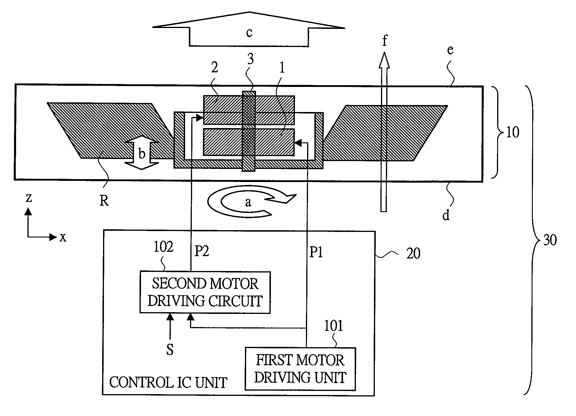
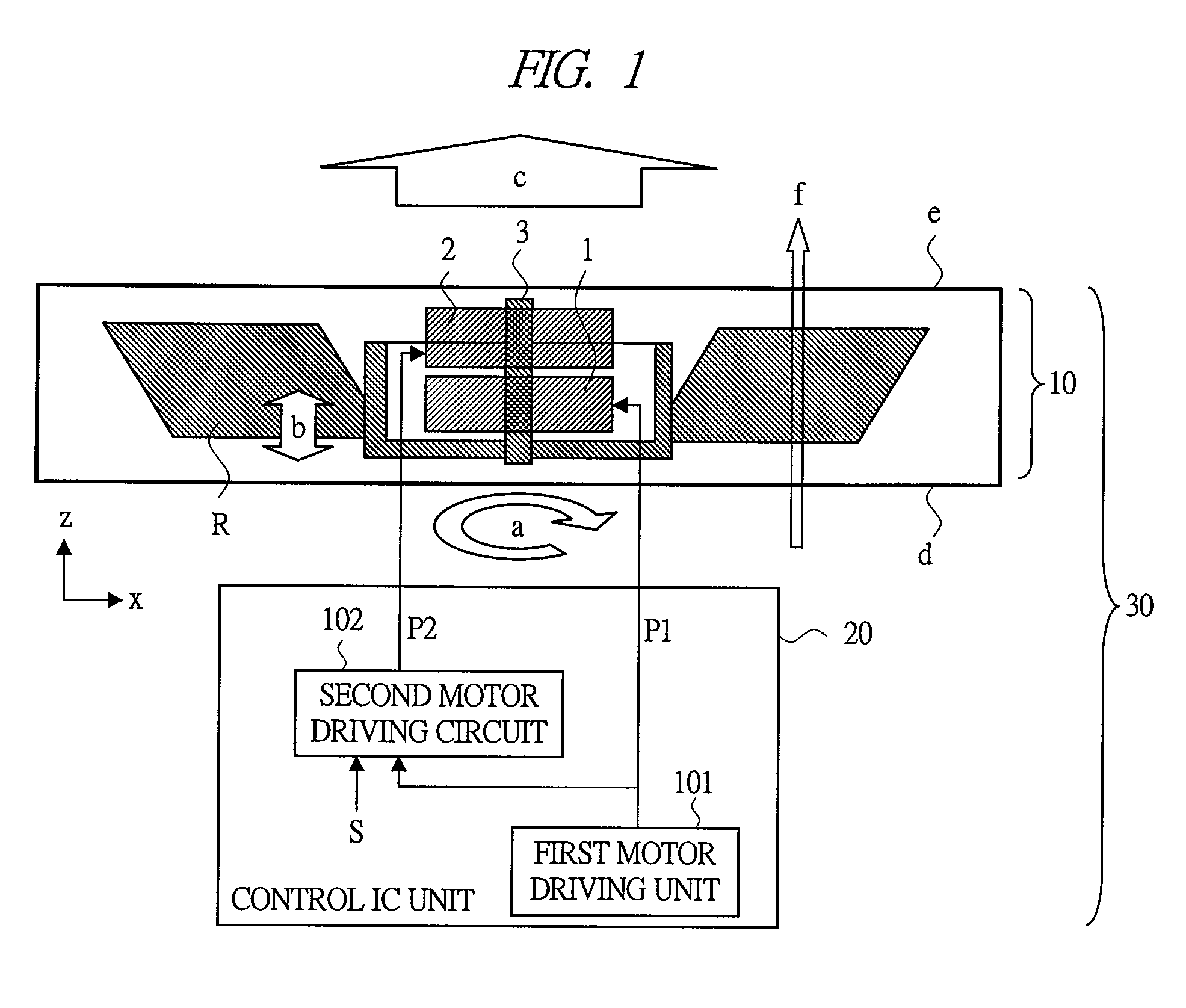
[0056]An electronic device 30A of the first embodiment (first configuration) of the present invention will be described with reference to FIG. 3 to FIGS. 7A to 7D, etc. The electronic device 30A has a fan 10A and a control IC unit 20A. FIG. 3 shows a cross section and a schematic configuration of the fan 10A, FIG. 4 shows details of the structure of the fan 10A (particularly, motor) in FIG. 3, FIG. 5 shows a planar configuration example viewed from the surface e of an exhaust opening side of the fan 10A, FIG. 6 shows a circuit configuration example of the control IC unit 20A, and FIGS. 7A to 7D show examples of waveforms of control performed by the control IC unit 20A.

[0057]The first embodiment has the following configuration as an overview (note that, reference numerals are corresponding to the following description). The present device has, as basic noise reduction control by the control IC unit 20A, control performed by a combination of drive-control of the fan rotation (a) by th...

second embodiment

[0096]Next, an electronic device 30B (having a fan 10B and a control IC unit 20B) of the second embodiment of the present invention (second configuration) will be described with reference to FIG. 8, etc. The part different from the first embodiment will be mainly described. An overview of the second embodiment is as described below. In the fan 10B, as well as a speaker (conventional technique), a movable mechanism in the axial direction (z direction) is provided. More specifically, the rotating and vibrating unit R (including 3B, 4, 5) can be rotated (a) about a rotation axis 3B as a rotating body and can be vibrated (b) in the z direction as a vibrator. In addition to that, when the vibration (b) according to a reversed phase with respect to noise (outputted by the basic rotation (a)) of the fan 10B is provided, noise reduction control is performed. In other words, the rotating and vibrating unit R is used as a speaker function for noise reduction control by the vibration control i...

third embodiment

[0102]Next, an electronic device 30C (it comprises a fan 10C and a control IC unit 20C) of the third embodiment of the present invention (third configuration) will be described with reference to FIG. 9 and so forth. The part different from the first embodiment will be mainly described. The overview of the third embodiment is as described below. In the electronic device 30C, the fan 10C has a configuration in which a speaker 40 for noise reduction control is embedded instead of the VCM (second motor 2). To give an outline, the second motor 2 and the corresponding circuits are replaced by the speaker 40 and corresponding circuits in the configuration.

[0103]In the fan 10C, for vibration control in the direction (z direction) of a rotation axis 3C, the speaker 40 is provided at a center position of the rotating body (including 3C, 4, 5) in the exhaust opening surface e side. In addition to that, the vibration (b) corresponding to the reversed-phase sound with respect to the noise (outpu...


PUM


Abstract

An electronic device having a first motor which rotates a rotating body (for example, blades) about a rotation axis and a second motor which vibrates a vibrator including the rotating body in the axial direction is provided. A control IC unit has a first circuit which subjects the rotation to control drive by a first waveform, and a second circuit which subjects the vibration to control drive by a second waveform. Rotation and vibration of a rotating and vibrating unit driven by the first and second motors generates an airflow and output sound by a synthesized output of a first output corresponding to the rotation and a second output corresponding to the vibration. The control IC unit generates a second waveform by using a reversed-phase waveform with respect to the first waveform or the like and suppresses the output sound by control of the first and second waveforms.

Description

CROSS-REFERENCE TO RELATED APPLICATION[0001]The present application claims priority from Japanese Patent Application No. JP 2007-296506 filed on Nov. 15, 2007, the content of which is hereby incorporated by reference into this application.TECHNICAL FIELD OF THE INVENTION[0002]The present invention relates to a fan (blower) and an electric / electronic device, information-processing apparatus and the like having a fan. More particularly, the present invention relates to a technique of noise reduction.BACKGROUND OF THE INVENTION[0003]Along with performance improvement of electronic devices, heat generation thereof has been increased as well. If the heat is left untreated, it invites a situation in which the failure of the device, performance deterioration, shortened life time and so on. Therefore, the device has to be equipped with a cooling function. Generally, a fan is used for the cooling function. Examples of the means for enhancing the cooling performance of a fan include increasin...

Claims


Application Information

Patent Timeline
Patent Type & Authority Patents(United States)
IPC IPC(8): G10K11/16F24F13/24F01D25/04F04D29/66
CPCF04D29/661F04D29/663F04D29/665F04D33/00F04D25/0646F04D29/005F04D25/064F04D25/0633H02P6/00F04D29/052
Inventor YOKOYAMA, NOBUHIROCHIKUSA, TAKASHIIWAKURA, MASAO
Owner HITACHI LTD
Why Eureka
Try Eureka