
Vehicle periphery monitoring apparatus

a monitoring apparatus and periphery technology, applied in anti-collision systems, external condition input parameters, special data processing applications, etc., can solve the problems of difficult to view an object diagonally and recognize a ground plane, and difficulty in recognizing a ground plane,

Inactive Publication Date: 2011-04-12
MITSUBISHI MOTORS CORP
View PDF25 Cites 29 Cited by
  • Summary
  • Abstract
  • Description
  • Claims
  • Application Information

AI Technical Summary

Benefits of technology

The present invention is a system for monitoring the area around a vehicle using a camera and special software. The system can detect feature points in the images and calculate their movement. It can also detect objects that are approaching the vehicle and track them as they move. The system can also determine the time it takes for the approaching object to pass by the vehicle. This invention can help drivers see what is happening around their vehicle, making it safer to drive.

Problems solved by technology

In general, however, it is difficult to recognize a ground plane on an image.
Therefore, a ground plane to be recognized is limited to a ground plane of an automobile on an image shot from the front or rear.
In general, however, it is difficult to view an object diagonally and recognizing a ground plane in order to recognize an approaching object included in the visual field as in the case of the above-mentioned nose view monitoring apparatus.
Also, it cannot be denied that measuring the distance to a moving object using a combination of a distance sensor and a camera as in the case of the vehicle camera apparatus disclosed in Patent Document 5 makes the apparatus expensive.

Method used


Image

  • Vehicle periphery monitoring apparatus
  • Vehicle periphery monitoring apparatus
  • Vehicle periphery monitoring apparatus

Examples


Embodiment Construction

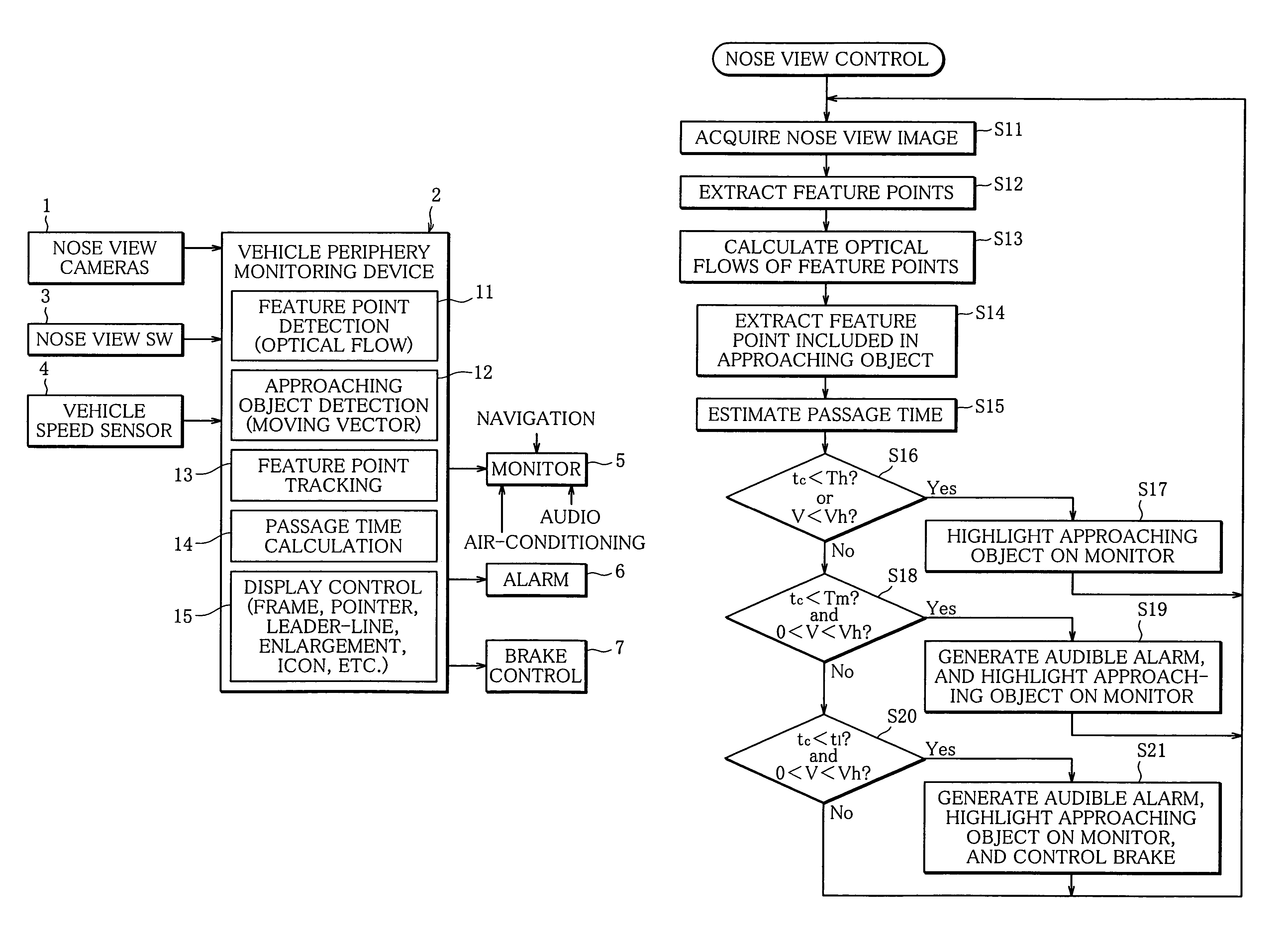
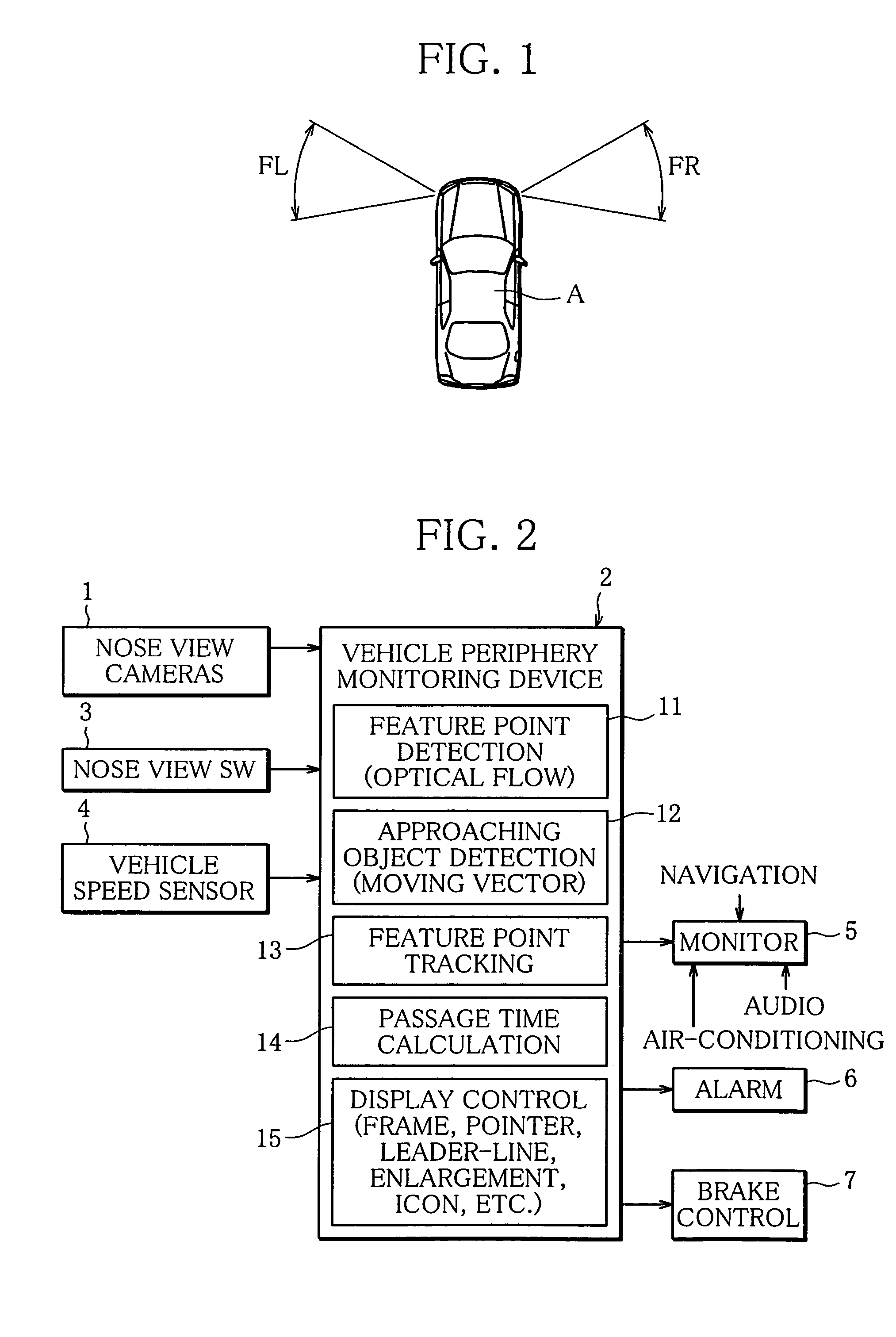
[0023]The present invention will now be described in detail with reference to the drawings showing an embodiment thereof. FIG. 2 is a block diagram schematically showing the configuration of the principal part of a vehicle periphery monitoring apparatus according to an embodiment of the present invention. In FIG. 2, reference numeral 1 denotes a pair of nose view cameras incorporated in the front of a vehicle, for picking up right and left views on both sides of the vehicle. The nose view cameras 1 are comprised of, for example, CCD cameras incorporated in both sides of the front end of a vehicle A as shown in FIG. 1, and are disposed to pick up predetermined right and left views FL and FR on both sides of the vehicle A. Alternatively, the nose view cameras 1 may be incorporated in the rear of a vehicle, for picking up right and left views on both sides of the vehicle.

[0024]A periphery monitoring device 2 that captures side images (nose view images) picked up by the nose view camera...


PUM


Abstract

A vehicle periphery monitoring apparatus is comprised of a camera installed in the front or rear of a vehicle, for picking up images of side view of the vehicle; a feature point detecting section that detects feature points in the side images and calculates the motion vectors of the detected feature points; a moving object detecting section that detects a set of a plurality of feature points approaching the vehicle in the side images as an approaching object based on the calculated motion vectors of the feature points; a feature point tracking section that tracks the feature points of the detected approaching object; and a passage time calculating section that calculates the time at which the approaching object passes the front or rear of the vehicle from the feature points of the approaching object tracked by the feature point tracking section.

Description

BACKGROUND OF THE INVENTION[0001]1. Field of the Invention[0002]The present invention relates to a vehicle periphery monitoring apparatus that monitors the periphery of a vehicle based on an approaching object captured by a camera installed in the vehicle.[0003]2. Description of the Related Art[0004]An example of apparatuses that monitor the periphery of a vehicle based on images picked up by a camera installed in the vehicle is disclosed in Japanese Laid-Open Patent Publication (Kokai) No. 2001-43494 (hereinafter referred to as Patent Document 1). In this vehicle peripheral monitoring apparatus, as shown in a conceptual diagram of FIG. 1, cameras (nose view cameras) incorporated in the front of a vehicle pick up side views FL and FR in front of the vehicle, which are likely to be blind spots as viewed from a driver seat. The picked-up side views are displayed on a monitor at the driver seat in the vehicle so that the driver can confirm safety, for example, when advancing the vehicl...

Claims


Application Information

Patent Timeline
Patent Type & Authority Patents(United States)
IPC IPC(8): G08G1/16G05D1/02G06F7/00B60R22/00H04N7/18G05D1/00G06K9/00G08B23/00B60Q1/00B60R1/00B60R11/02B60R21/00B60T7/12
CPCB60T7/22B60T2201/022B60W10/18B60W2550/20B60W40/04B60W2050/146B60W2420/42B60W30/08B60W2554/00B60W2420/403
Inventor MAEMURA, TAKAHIROIKEYAMA, MASAHIROSASANE, SHIGEYA
Owner MITSUBISHI MOTORS CORP
Learn More