Device for generating tire air pressure

a technology for air pressure generation and tires, applied in the direction of positive displacement liquid engines, pumps, machines/engines, etc., can solve the problem of inability to freely form air paths (discharge paths), and achieve the effect of enhancing the degree of freedom of design and enhancing the attaching workability of air pressure control valves

Inactive Publication Date: 2011-04-19
TOYOTA JIDOSHA KK
View PDF26 Cites 8 Cited by
  • Summary
  • Abstract
  • Description
  • Claims
  • Application Information

AI Technical Summary

Benefits of technology

[0005]In this case, the plug member can be attached to and detached from the hub of the vehicle. Thus, before the plug member is assembled to the hub of the vehicle, a portion of the air path (a portion of the discharge path) can be formed in the plug member. Therefore, a portion of the air path (a portion of the discharge path) can be formed without subjection to restriction imposed by the position (arrangement) of the pump chamber, thereby enhancing the degree of freedom of design of the air path (discharge path).
[0006]When the present invention is embodied, an air pressure control valve for controlling compressed air to be supplied from the pump chamber to the tire air chamber through the air path may be assembled to the plug member. In this case, as compared with the case where the air pressure control valve is assembled to the hub of the vehicle, the degree of freedom of design of the air pressure control valve can be enhanced, and the attaching workability of the air pressure control valve can be enhanced.
[0007]Further, in this case, the air pressure control valve may have adjustment means for adjusting a set value of pressure for compressed air which is output under control by the air pressure control valve. In this case, the pressure of compressed air to be supplied to the tire air chamber can be set arbitrarily. Also, the adjustment means, together with the air pressure control valve, can be incorporated into the plug member, thereby enhancing the workability of attachment to the hub of the vehicle.
[0008]In this case, the adjustment means may include a female screw provided on the plug member, and a male screw which is screw-engaged with the female screw in such a manner as to be able to advance and retreat and can be rotated from outside the plug member. In this case, the adjustment means can be configured simply and at low cost.

Problems solved by technology

Therefore, because of restriction imposed by the position (arrangement) of the pump chamber, the air path (discharge path) cannot be freely formed.

Method used


Image

  • Device for generating tire air pressure
  • Device for generating tire air pressure
  • Device for generating tire air pressure

Examples


Embodiment Construction

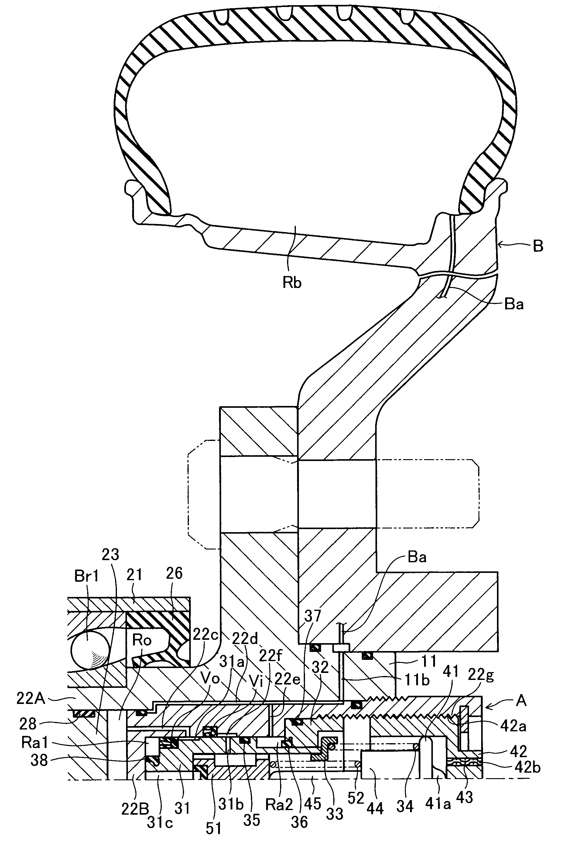
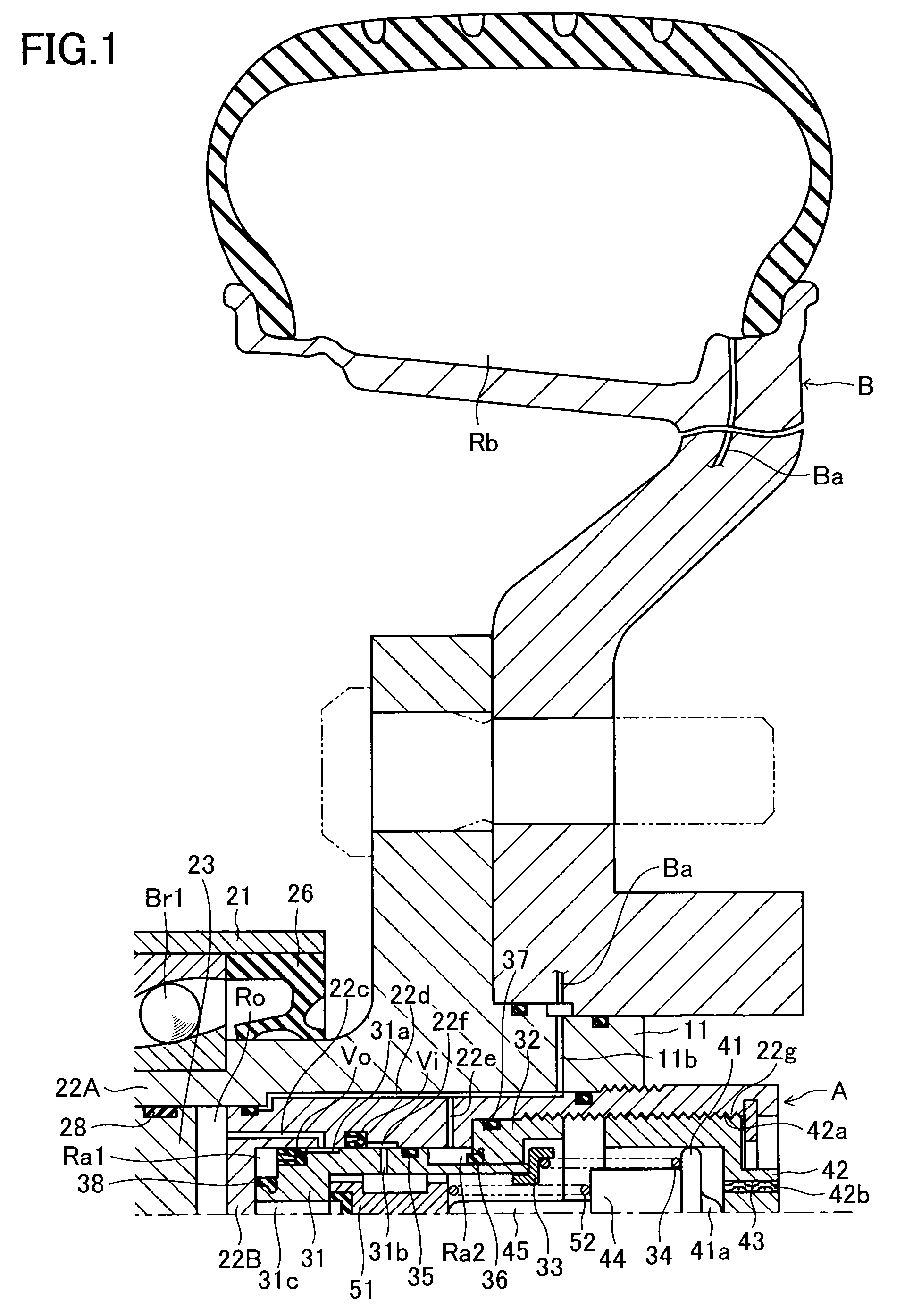
[0011]An embodiment of the present invention will next be described with reference to the drawings. FIGS. 1 and 2 show an embodiment in which a tire-air-pressure-generating apparatus A of the present invention is assembled to an axle hub 11 which rotates with a wheel B. A drive axle 12 is splined to the inboard end of the axle hub 11, whereby the axle hub 11 and the drive axle 12 are connected for torque transmission. The connection between the axle hub 11 and the drive axle 12 is ensured by means of a lock nut 13.

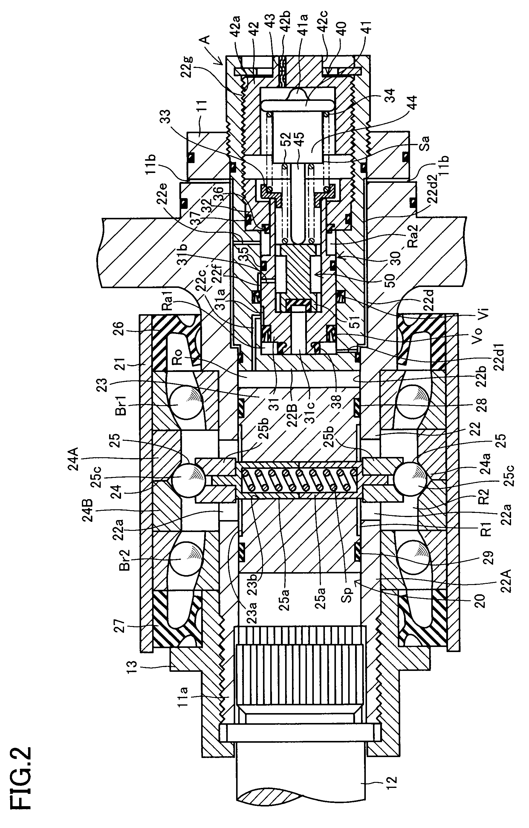
[0012]The tire-air-pressure-generating apparatus A includes an air pump 20, a pressure control valve 30, and an adjuster 40, which are coaxially disposed in a shaft portion (rotation shaft) 11a of the axle hub 11. The tire-air-pressure-generating apparatus A also includes a relief valve 50 coaxially disposed inside the pressure control valve 30. Of the air pump 20, the pressure control valve 30, and the adjuster 40, the air pump 20 is disposed at the furthest inboard posit...


PUM


Abstract

A tire-air-pressure-generating apparatus includes an air pump, a pressure control valve, and an adjustment device, which are disposed coaxially in a shaft portion of an axle hub. The air pump includes a pump chamber located in the interior of the axle hub. The pressure control valve and the adjustment device are assembled into a cylinder head, which is assembled airtightly and removably to the axle hub. The cylinder head includes a suction-discharge path, discharge paths, pressure lead paths, and a suction path.

Description

TECHNICAL FIELD[0001]The present invention relates to an apparatus for generating tire air pressure (hereinafter referred to as a “tire-air-pressure-generating apparatus”), and more particularly, to a tire-air-pressure-generating apparatus configured such that a pump chamber of an air pump is provided in the interior of a hub of a vehicle (e.g., an axle hub or a hub section of a wheel of the vehicle), and capable of supplying compressed air from the pump chamber to a tire air chamber of the wheel through an air path.BACKGROUND ART[0002]A tire-air-pressure-generating apparatus of such a type is disclosed in, for example, Japanese Patent Application Laid-Open (kokai) No. 1-172003. In the tire-air-pressure-generating apparatus described in this publication, a pump unit is disposed in a hub section of a wheel (composed of a wheel body and a tire); i.e., a hub section (a central portion) of the wheel body), and carries out a reciprocating motion in the axial direction of an axle while on...

Claims


Application Information

Patent Timeline
Patent Type & Authority Patents(United States)
IPC IPC(8): B60C23/12
CPCB60C23/12F04B9/04F04B35/01F04B35/00F04B9/047B60C23/127B60C23/137
Inventor ISONO, HIROSHI
Owner TOYOTA JIDOSHA KK
Why Eureka
Try Eureka