Piston assembly and a force transfer device, particularly a force transfer device with a piston assembly

a technology of force transfer device and piston assembly, which is applied in the direction of fluid gearing, coupling, belt/chain/gearing, etc., can solve the problems of power loss, achieve the effect of facilitating parallel operation mode, low effort, and high pressure in the piston assembly

Inactive Publication Date: 2011-04-19
SCHAEFFLER TECH AG & CO KG
View PDF3 Cites 8 Cited by
  • Summary
  • Abstract
  • Description
  • Claims
  • Application Information

AI Technical Summary

Benefits of technology

[0006]Through the solution according to the invention it is possible to avoid a direct connection and support of the clutch elements at the housing, and to create an independent operating device for the particular clutch devices, which is free from axial force effects, imparted upon the connecting elements, connected directly to said clutch devices. Thus, in a particularly advantageous embodiment, one of the clutches is disposed, so that it is possible to set a higher pressure in it, than in the surrounding area. This type of support is realized through a piston assembly according to this invention, comprising a first piston element, associated with the first actuatable clutch device, and a second piston element, associated with the second actuatable clutch device, wherein the second piston element is guided at the first piston element, so it is movable in axial direction, forming a pressure chamber with it, which can be pressurized with pressure means, wherein this pressure chamber is airtight and leak proof relative to the inner cavity of the housing. Furthermore, one respective clutch component of the first and the second actuatable clutch device is arranged at the piston element, so that the arrangement can be performed here completely detached from an arrangement inside the housing, this means, from a direct non-rotatable connection of these clutch elements with the housing. Thus, the piston arrangement is optional with respect to its position in axial direction in the force transfer device. This allows for different actuation concepts, as well as for a space saving arrangement of the piston assembly.
[0008]The force transfer device comprises at least one hydrodynamic component and one actuatable clutch device in the form of a lockup clutch. Furthermore, one additional actuatable clutch device is provided. It forms a first actuatable clutch device for the piston assembly, wherein the first actuatable clutch device in a multi function unit is preferably formed by a pump shell clutch for optional coupling or decoupling the pump shell with or from the input of the force transfer device, or a drive engine, coupled therewith, thus facilitating the de-coupling of the hydrodynamic component. After this de-coupling, merely the turbine shell of the hydrodynamic component is still coupled to the output non-rotatably and is dragged along. The second actuatable clutch device is formed by the lockup clutch. Thus it is arranged in a way, which leads to the piston force of the lockup clutch being supported in one direction indirectly at the piston of the pump shell clutch, and the closing force simultaneously acting upon the pump shell clutch in the other direction. Depending on the design, this either leads to the automatic disengagement of the pump shell clutch with the actuation of the lockup clutch through the design of the pressure conditions, or it remains actuated at a higher pressure. The piston assembly is thus supported non-rotatably at the transmission input shaft, which forms the output. This support can be performed directly or indirectly, preferably it is performed by an element, coupled non-rotatably with the gearbox output, provided as a hub. The piston assembly is thus axially fixated in one direction. Thus it is sufficient to utilize a combined axial- and radial bearing, which is associated with the first piston element, supporting it in axial direction at the face side, facing away from the second piston element. The support in the other direction thus occurs indirectly through providing a fixed stop at the first piston element, through which the second piston element and a component of the second actuatable clutch device are supported. Furthermore one respective clutch component of the first and the second actuatable clutch device is located in the first piston element, or the piston element carries them.

Problems solved by technology

When the drive engine is idling, particularly in coasting mode, the drive engine can be separated from the output by the lockup clutch, however, with a filled hydrodynamic component, which is the case for the hydrodynamic speed / torque converter also in bridged mode, torque is still being transferred into the hydrodynamic component, which results in a power loss when the engine is idling.

Method used


Image

  • Piston assembly and a force transfer device, particularly a force transfer device with a piston assembly
  • Piston assembly and a force transfer device, particularly a force transfer device with a piston assembly
  • Piston assembly and a force transfer device, particularly a force transfer device with a piston assembly

Examples


Embodiment Construction

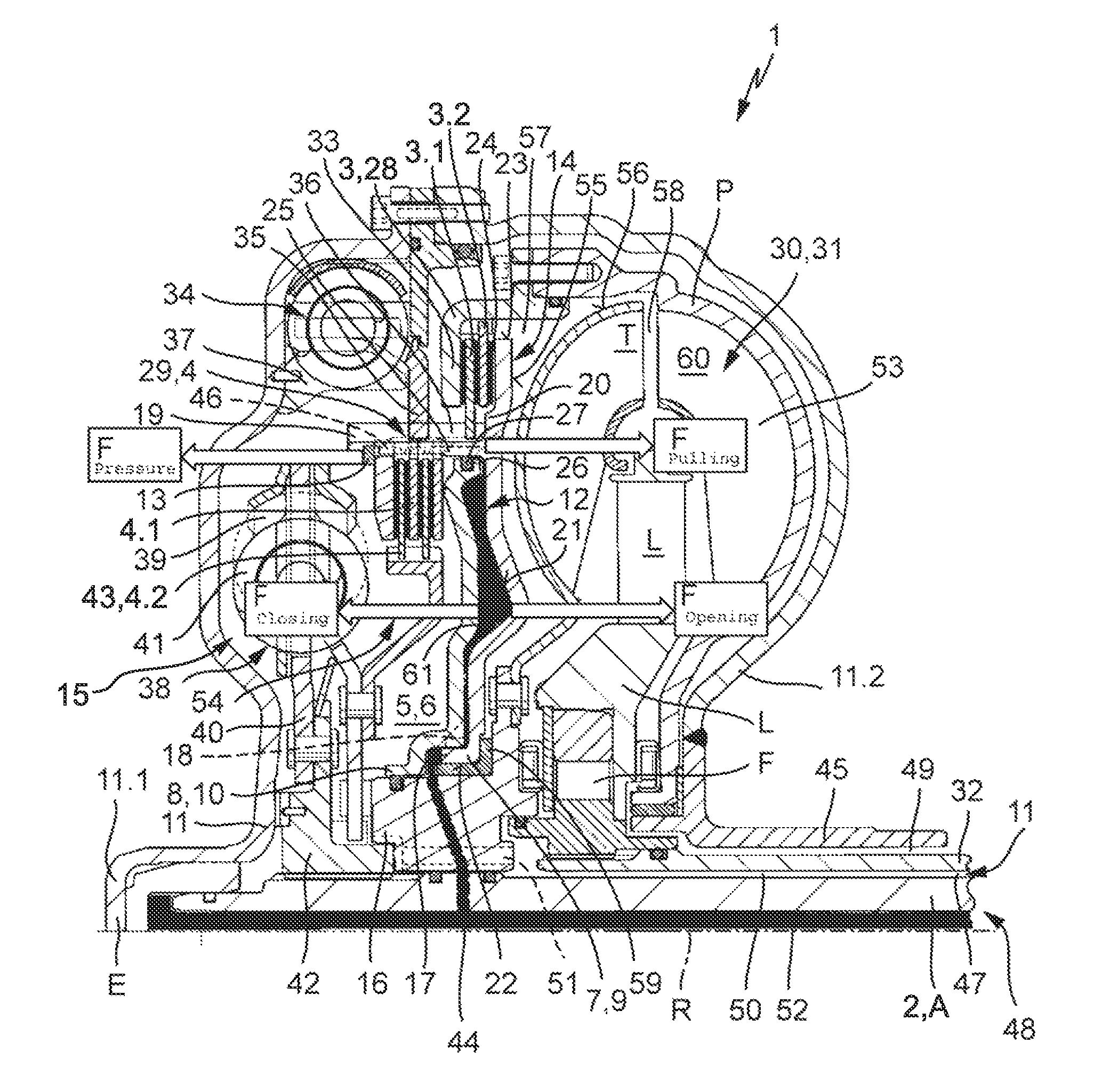
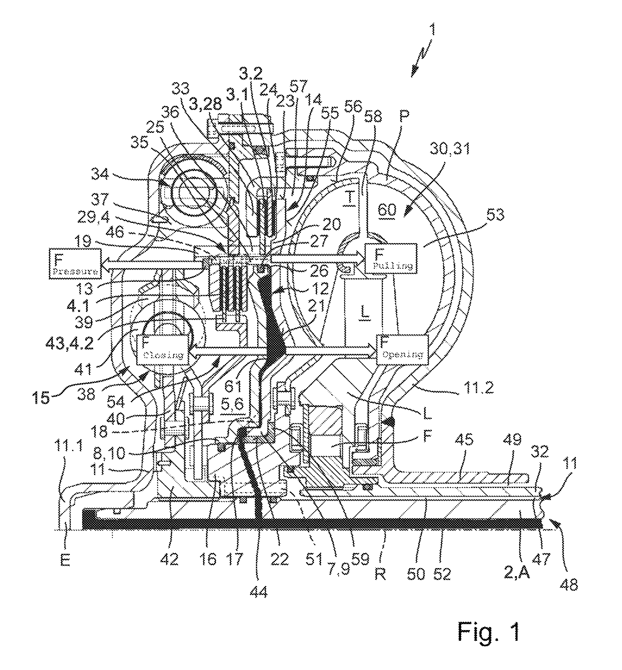
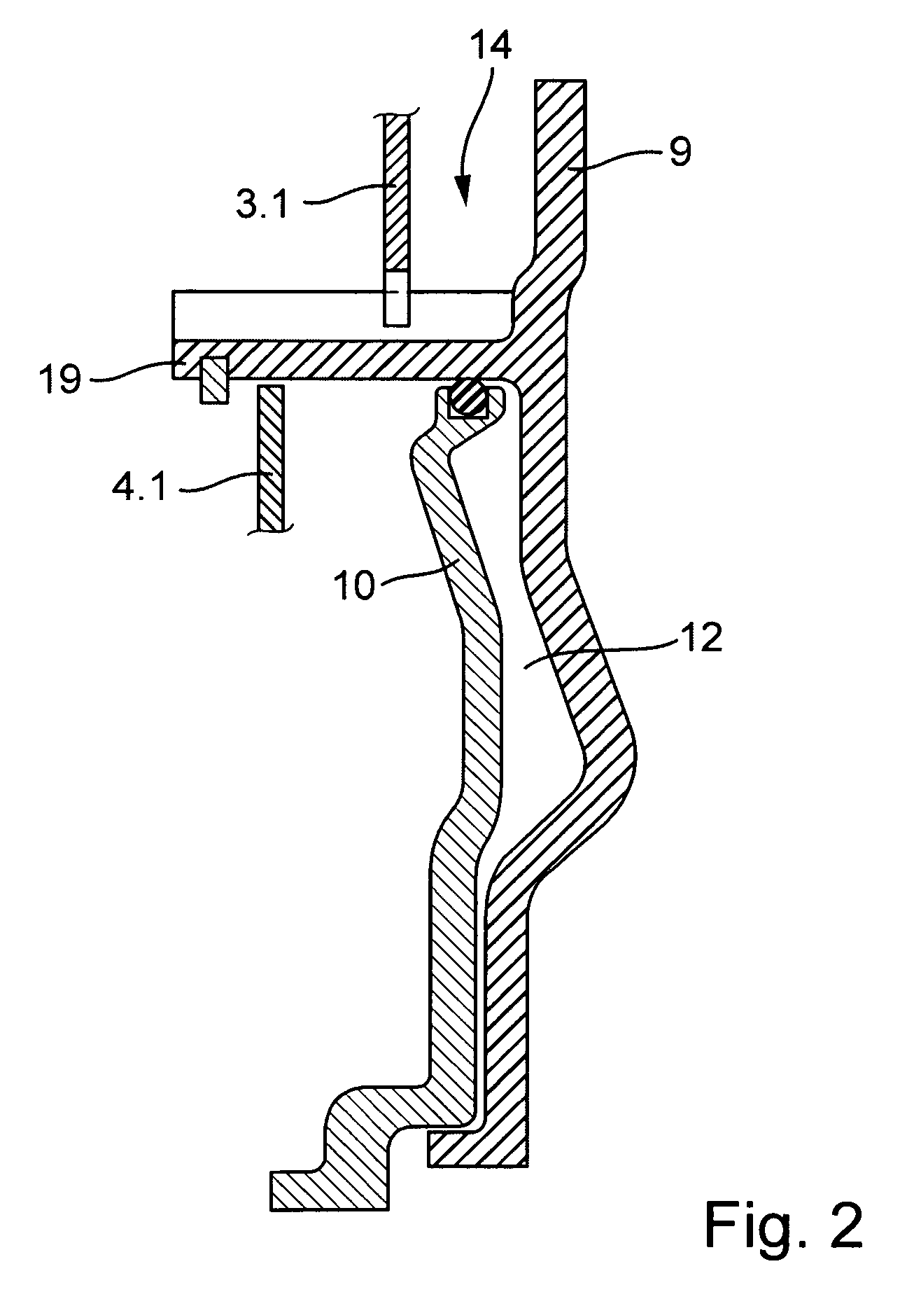
[0013]FIG. 1 illustrates an embodiment of force transfer device 1 according to the invention with reference to an axial cross section for arrangement in a drive train between a drive engine and a transmission, comprising input E and output A, wherein output A is formed by shaft 2 in the form of a transmission input shaft. It comprises two actuatable clutch devices between input E and output A, first actuatable clutch device 3 and second actuatable clutch device 4. The particular actuatable clutch devices 3 and 4 thus comprise at least first clutch component 3.1, or 4.1 and second clutch component 3.2 or 4.2, wherein the two clutch components 3.1 and 3.2 or 4.1 and 4.2 can be brought into at least indirect operative engagement. At least indirect means direct or indirect in this case. This depends on the design of clutch components 3.1, 3.2 or 4.1, 4.2. Two actuatable clutch devices 3 and 4 are thus arranged in inner space 6 of force transfer device 1, forming cavity 5, which can be l...


PUM


Abstract

A piston assembly for arrangement in a pressure cavity in a force transfer device for operating a first and a second actuatable clutch device, comprising a piston element associated respectively with an actuatable clutch device. The invention is characterized in that the piston element of the second clutch device is guided at the piston element of the first clutch device movable against a stop, forming an additional second cavity, loadable with pressure medium, wherein the first piston element is movable in an axial direction, relative to the piston element of the second clutch device.

Description

CROSS REFERENCE TO RELATED APPLICATIONS[0001]This patent claims priority of German Patent Application No. 10 2006 061 552.2, filed on Dec. 27, 2006 and German Patent Application No. 10 2006 061 553.0, filed on Dec. 27, 2006, which applications are incorporated herein by reference.FIELD OF THE INVENTION[0002]The invention relates to a piston assembly for operating two actuatable clutch devices in a force transfer device; furthermore it relates to a force transfer device, in particular a force transfer device with such piston assembly.BACKGROUND OF THE INVENTION[0003]Force transfer devices, which are disposed between a drive engine and a transmission unit, are known in a plurality of embodiments in the state of the art. They typically comprise an input and at least one output, wherein the input can be coupled to a drive engine at least indirectly, this means directly, or through further transfer elements, and at least one output, which is coupled to a transmission unit, which is dispo...

Claims


Application Information

Patent Timeline
Patent Type & Authority Patents(United States)
IPC IPC(8): F16D25/10F16H45/02
CPCF16D25/0638F16D25/10F16H45/02F16H2045/002F16H2045/0284F16H2045/0247F16H2045/0252F16H2045/0257F16H2045/0226F16D21/06
Inventor KOMBOWSKI, EUGEN
Owner SCHAEFFLER TECH AG & CO KG
Why Eureka
Try Eureka