Electronic circuit for a contactless reader device

a reader device and electronic circuit technology, applied in the field of electronic circuits for reader devices, can solve problems such as failure to deal with the input stage of a reading device, and achieve the effects of reducing the input voltage, preventing damage to the sensitive receiving module, and increasing the degree of freedom

Active Publication Date: 2011-04-19
QUOTAINNE ENTERPRISES
View PDF5 Cites 6 Cited by
  • Summary
  • Abstract
  • Description
  • Claims
  • Application Information

AI Technical Summary

Benefits of technology

[0013]The above-stated measures provide the advantage that the receiving module can operate in an optimum operating range although the matching between electric circuit and antenna circuit as well as the environmental conditions around the reading device may vary.
[0014]In an advantageous embodiment of the invention, an adjustable damping element is arranged between said receiving module and said antenna connection, and said control module is arranged to compare said input voltage to a reference value and to adjust said damping element accordingly. Quite often it is necessary to downscale the antenna voltage, which may reach amplitudes up to 100V, to a level which is feasible for the receiving module. Dependent on the technology used, the input voltage should be in the range of some volts. As a damping element in principle is comprised in the reader devices currently used, the invention can be realized in a relatively simple manner by exchanging the existing damping element (which generally is a voltage divider) for an adjustable damping element, e.g. a (digitally controlled) potentiometer.
[0016]In a very advantageous embodiment of the invention, an adjustable damping element is arranged between said receiving module and said antenna connection, an adjustable amplifier is arranged to drive said antenna, and said control module is arranged to compare said input voltage to a reference value and to adjust said damping element and said amplifier accordingly. Here, both methods, which were presented before, are combined, thus providing an increased degree of freedom. Furthermore, a greater variation of the disturbing parameters, that is to say a poor matching of the antenna circuit as well as unfavorable environmental conditions, may be compensated due to the additional effect of both possibilities of adjustment.
[0017]In yet another beneficial embodiment, the plant(s) of the reader device is (are) set to a start value, to adjust said plant(s) step by step in such a way that the level of the input voltage increases and to stop the adjustment when a predefined level of the input voltage is reached. Here, starting at the low side, the antenna voltage and, in turn, the input voltage are increased, thus preventing damage to the sensitive receiving module. However, it is also imaginable to start at the upper side and adjust said plant(s) step by step in such a way that the level of the input voltage decreases. When the optimum level is reached, the sequence is stopped, as satisfactory operation of the receiving module is obtained. The final adjustment can also be stored in a memory of the electric circuit for later use, e.g. for a later power-up of the reader device. The control module used therefore preferably comprises a microprocessor or a state machine.

Problems solved by technology

One problem which is to be overcome when designing a reader device relates to the question how to handle different boundary conditions of the systems, that is to say: varying distances between reader device and transponder, varying environmental conditions (disturbing objects in the radio range), and last but not least different design guidelines, which could mean that the developer has to use a special electric reader circuit with a special antenna.
However, WO 99 / 43096. fails to deal with the input stage of a reading device.

Method used


Image

  • Electronic circuit for a contactless reader device
  • Electronic circuit for a contactless reader device
  • Electronic circuit for a contactless reader device

Examples


Embodiment Construction

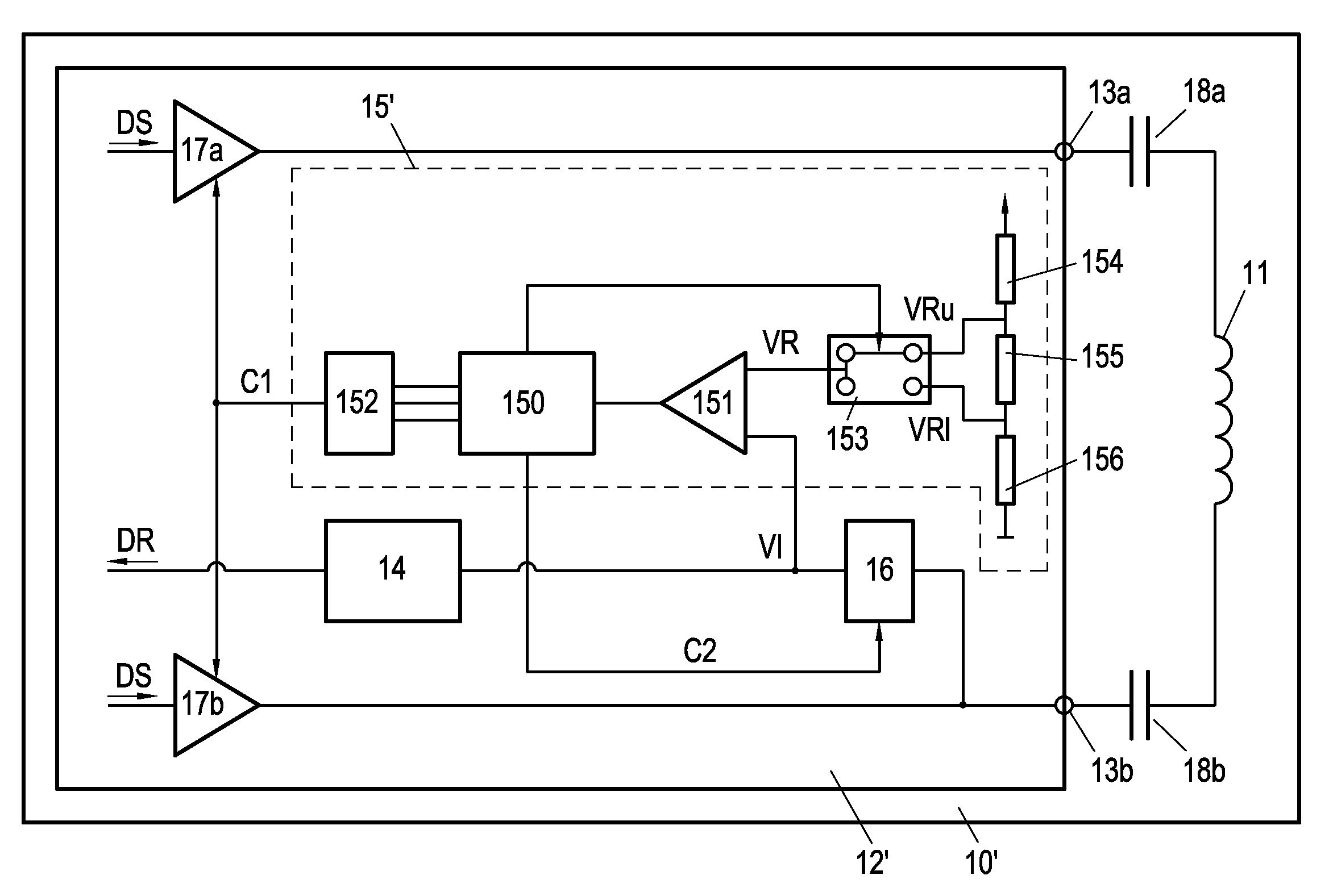
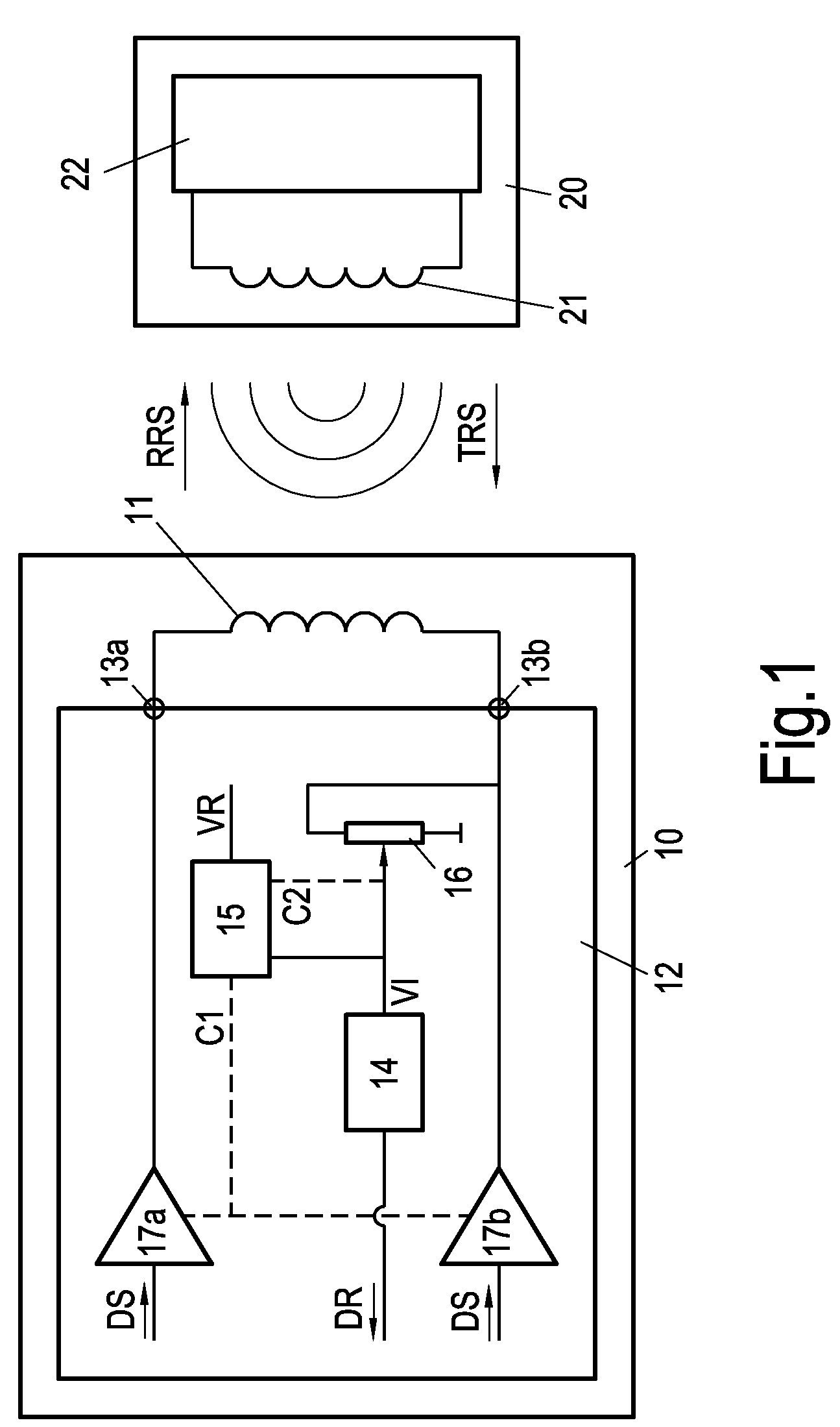
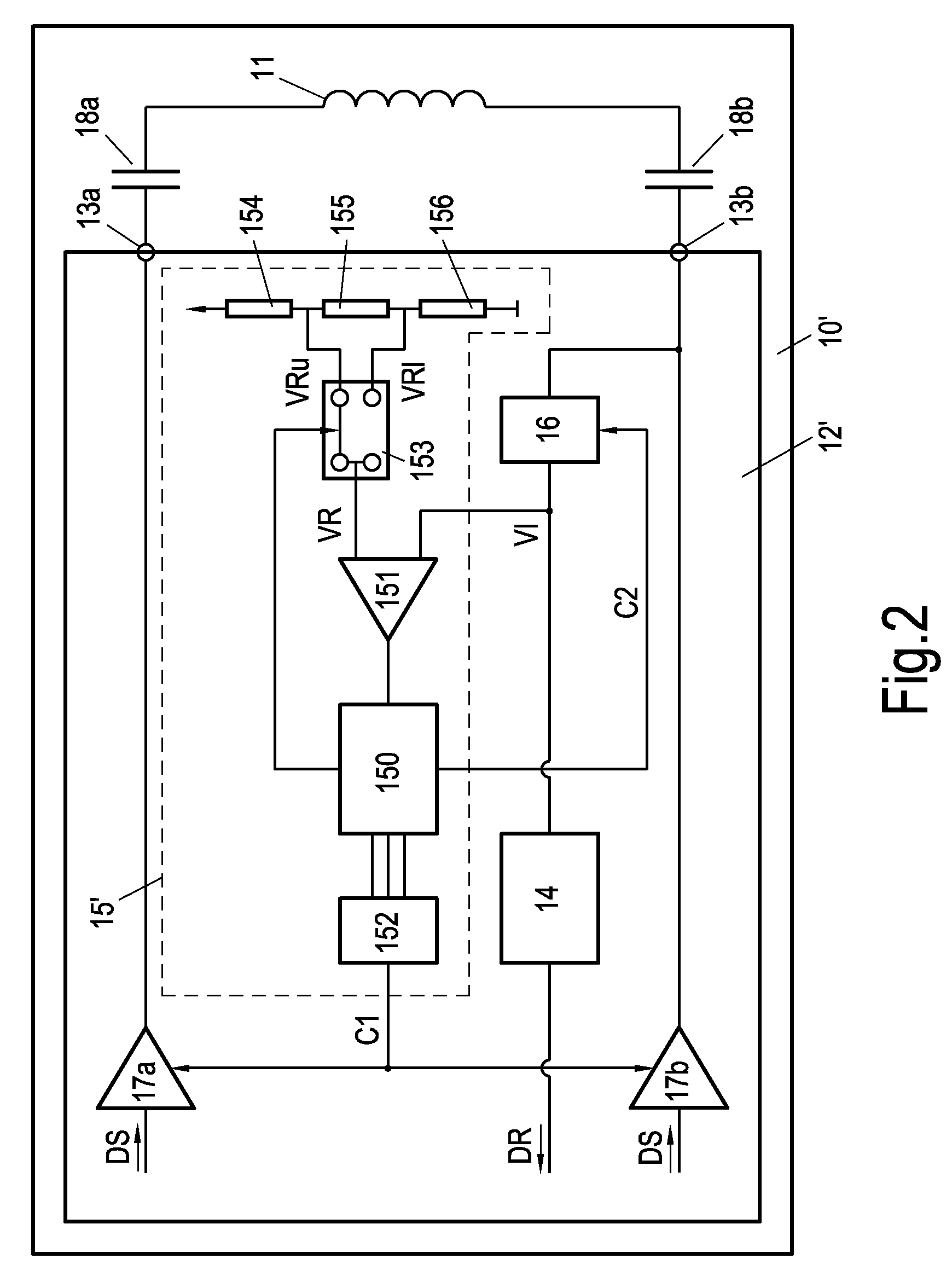
[0027]FIG. 1 shows a reader device 10 in communication with a transponder 20, which transponder 20 comprises a transponder antenna 21 and a transponder circuit 22. Accordingly, the reader device 10 comprises an antenna 11 and an electronic circuit 12. The electronic circuit 12 itself is connected to the antenna 11 by means of connections 13a, 13b. Inside the electronic circuit 12 there are a receiving module 14, a control module 15, a damping element 16 and a first and a second amplifier 17a, 17b. The first connection 13ais connected with an output of the first amplifier 17a. Accordingly, the second connection 13b is connected with an output of the second amplifier 17b. In addition, the second connection 13bis connected with an input of the receiving module 14, with the damping element 16 being arranged in-between. The input of the receiving module 14 is furthermore connected to an input of the control module 15. Outputs of the control module 15 are shown in dashed form. One output ...


PUM


Abstract

An electronic circuit (12, 12′) for a reader device (10, 10′) for contactless communication with a transponder (20) is disclosed. The electronic circuit (12, 12′) comprises a connection (13a, 13b) to an antenna (11) of said reader device (10, 10′), which antenna (11) is designed for receiving a radio signal (TRS) from said transponder (20). Furthermore, it comprises a receiving module (14), which is connected to the antenna connection (13a, 13b) and arranged for processing an input voltage (VI) from said antenna (11) representing said radio signal (TRS). To provide satisfactory operation of the receiving module (14) and to compensate a bad matching of the antenna circuit to the electronic circuit (12, 12′) and / or bad environmental conditions where the reader device (10, 10′) is operated, the electronic circuit furthermore comprises a control module (15, 15′). Said control module (15, 15′) is arranged to compare said input voltage (VI) to a reference value (VR) and to adjust a plant of said reader device (10, 10′) in such a manner that the level of said input voltage (VI) stays in a predefined range. The invention furthermore relates to a reader device (10, 10′) and a method of operating a reader device (10, 10′).

Description

FIELD OF THE INVENTION[0001]The invention relates to an electronic circuit for a reader device, which reader device is designed for contactless communication with a transponder, the circuit comprising a connection to an antenna of said reader device, which antenna is designed for receiving a radio signal from said transponder, and comprising a receiving module connected to the antenna connection and arranged for processing an input voltage from said antenna representing said radio signal.[0002]The invention furthermore relates to a reader device designed for contactless communication with a transponder, comprising an inventive electronic circuit and an antenna connected thereto, and finally to a method of controlling a range of an input voltage of a receiving module comprised by a reader device, which reader device is designed for contactless communication with a transponder.BACKGROUND OF THE INVENTION[0003]Contactless reader devices as defined in the opening paragraph are broadly u...

Claims


Application Information

Patent Timeline
Patent Type & Authority Patents(United States)
IPC IPC(8): G06K7/00
CPCG06K7/0008
Inventor SPIESS, BERNHARDERDENIZ, PAMIRZENZ, MICHAEL
Owner QUOTAINNE ENTERPRISES
Why Eureka
Try Eureka