
Process challenge device for assessing the effective performance of a biocontamination deactivation process

a biocontamination deactivation and process technology, applied in the field of monitoring a biocontamination deactivation process, can solve the problems of difficult to expose the inner surface of the lumen the microbial deactivation process may not be effective, and the surface of medical instruments is difficult to expose to so as to improve the circulation of the vaporous deactivating agent and the effect of reducing the condensation of a

Active Publication Date: 2011-04-19
AMERICAN STERILIZER CO
View PDF25 Cites 10 Cited by
  • Summary
  • Abstract
  • Description
  • Claims
  • Application Information

AI Technical Summary

Benefits of technology

[0011]An advantage of the present invention is the provision of a PCD for determining the effectiveness of a deactivation process that uses vaporized hydrogen peroxide to microbially deactivate medical instruments.
[0012]Another advantage of the present invention is the provision of a PCD housing that includes a passageway with two (2) open ends.
[0013]Still another advantage of the present invention is the provision of a PCD housing including a passageway defined therein by walls that are resistant to collapse in response to pressure changes.
[0014]Still another advantage of the present invention is the provision of a PCD housing having a passageway defined therein that is arranged to minimize condensation of a vaporous deactivating agent therein.
[0015]Still another advantage of the present invention is the provision of a PCD housing providing improved circulation of a vaporous deactivating agent therein.
[0016]Yet another advantage of the present invention is the provision of a PCD housing that allows convenient removal of biological and / or chemical indicators from the PCD housing.

Problems solved by technology

Some surfaces of medical instruments are difficult to expose to the vaporous deactivating agent because of the shape, i.e., geometry, of the instrument.
For example, for instruments having lumens, it is difficult to expose the inner surfaces of the lumens to the vaporous deactivating agent.
As a result, a microbial deactivation process may not be effective because such surfaces have not been successfully deactivated by appropriate exposure to the vaporous deactivating agent.
One problem with existing PCD housings is that the passageway leading to the BI and / or CI can become partially or fully blocked, thereby causing the BI and / or CI to provide inaccurate results concerning the effectiveness of the microbial deactivation process.
The passageway within the housing can become blocked as the result of several conditions.
For example, condensation of the vaporous deactivating agent within the passageway can result in blockage of the passageway.
The passageway can also become blocked when the walls defining the passageway collapse or are drawn into the passageway in response to pressure changes during the microbial deactivation process.
A PCD having a passageway with a reduced diameter provides a challenge greater than the most difficult item to deactivate in the load.
Accordingly, the BI and / or CI may not provide accurate results.
Another problem with existing PCD housings is that the BI and / or CI of the PCD may not be exposed to the same concentration of vaporous deactivating agent (e.g., vaporized hydrogen peroxide) as the surfaces of the instruments being deactivated.
It is believed that this inconsistency results from inadequate circulation of the vaporous deactivating agent within the PCD housing, as compared to the circulation of vaporous deactivating agent within the item (e.g., a lumened instrument) being deactivated.

Method used


Image

  • Process challenge device for assessing the effective performance of a biocontamination deactivation process
  • Process challenge device for assessing the effective performance of a biocontamination deactivation process
  • Process challenge device for assessing the effective performance of a biocontamination deactivation process

Examples


Embodiment Construction

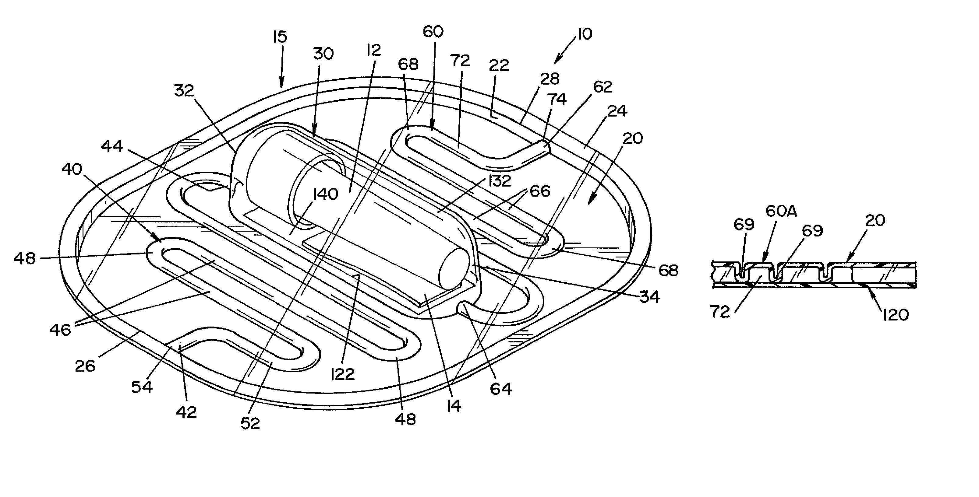
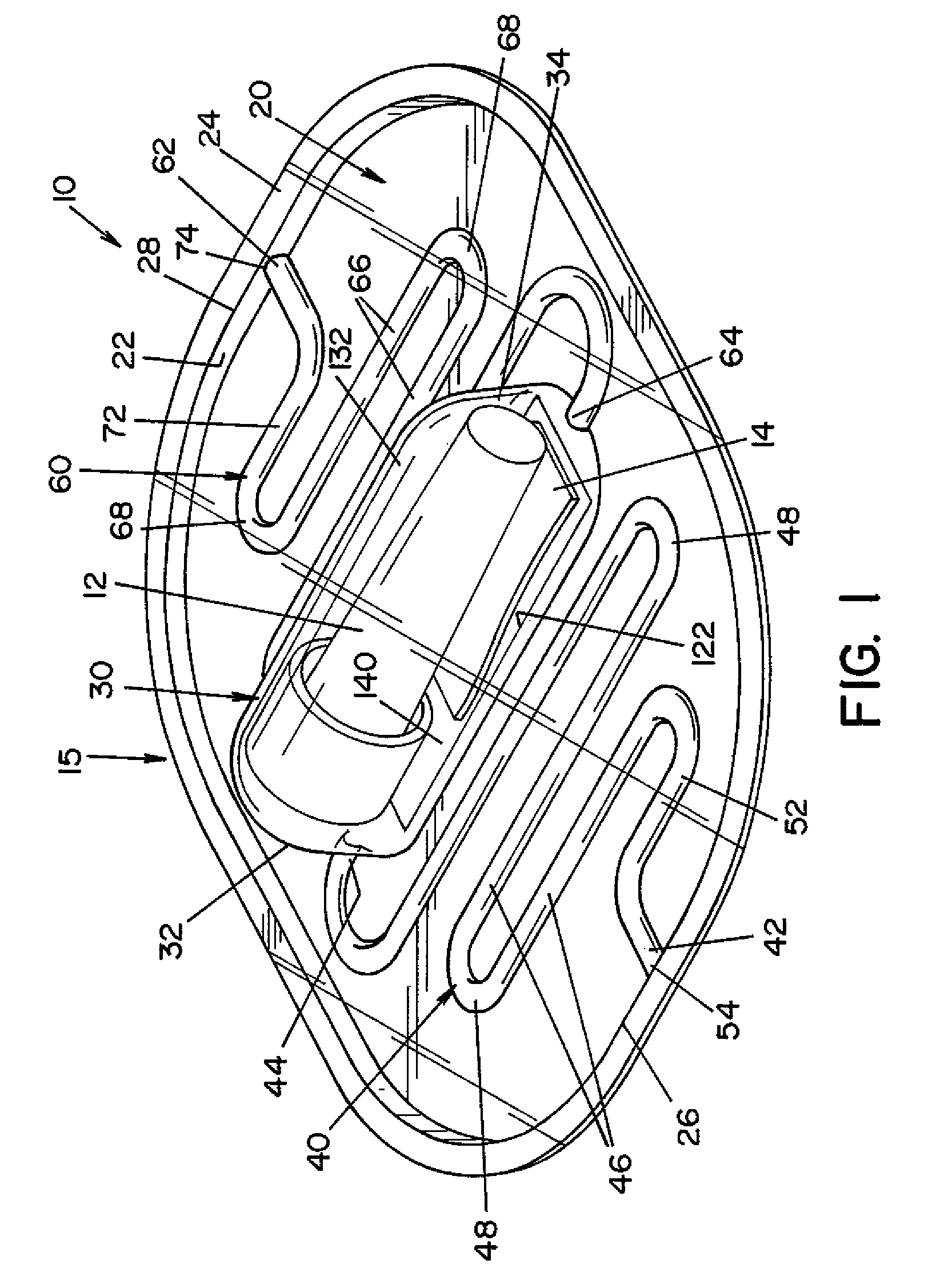
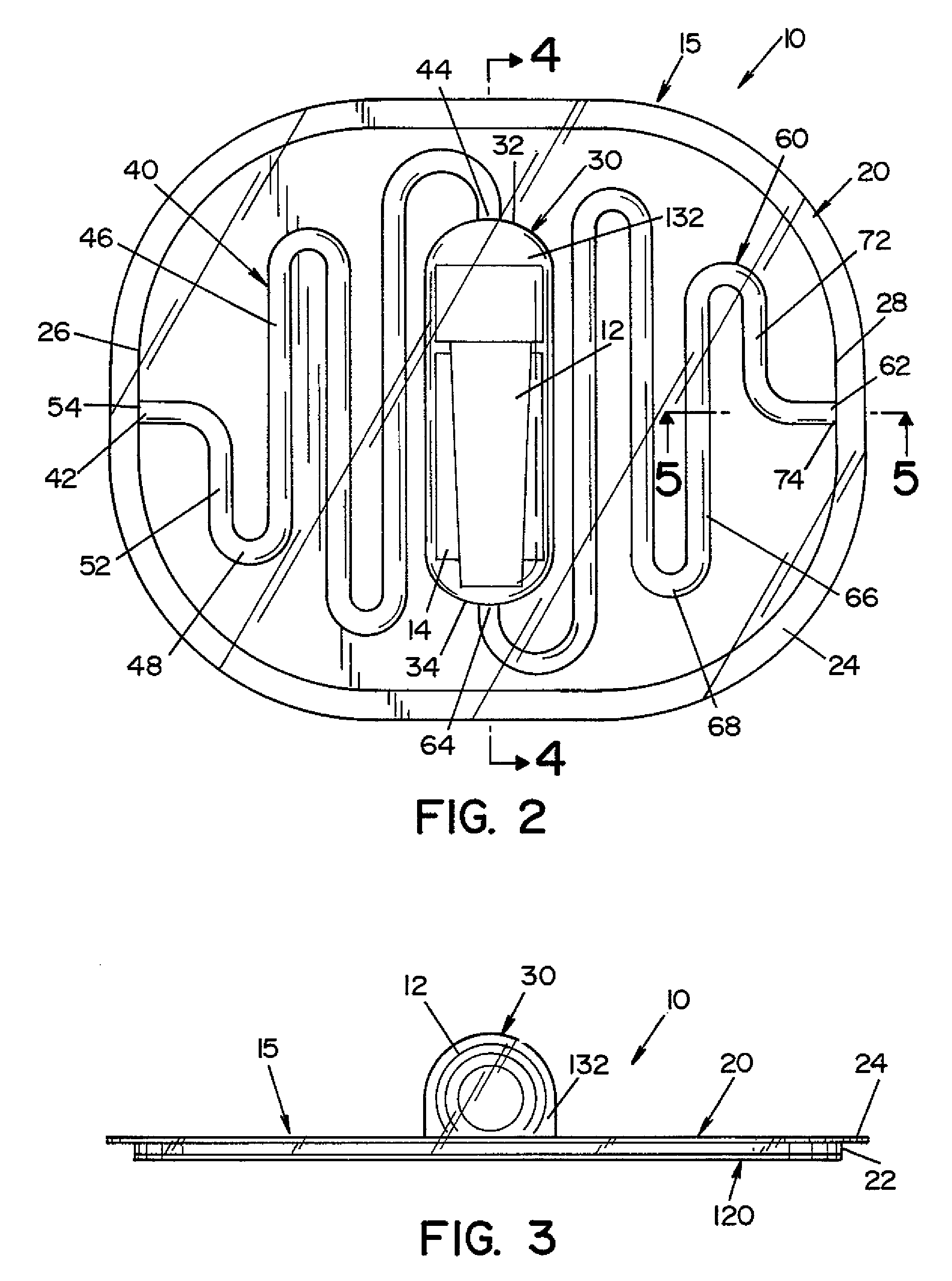
[0028]Referring now to the drawings wherein the showings are for the purpose of illustrating one embodiment of the invention only and not for the purpose of limiting same, FIGS. 1-3 show a process challenge device (PCD) 10 according to one embodiment of the present invention. PCD 10 includes a housing 15 and an indicator device, such as a biological indicator (BI) 12 and / or a chemical indicator (CI) 14. Housing 15 is generally comprised of a first layer 20 and a second layer 120, as best seen in FIGS. 3 and 6.

[0029]First layer 20 is a generally planar sheet having a first end 26 and a second end 28. In the illustrated embodiment, a side wall 22 extends from the peripheral edge of first layer 20, and a flange 24 extends outward from side wall 22. Side wall 22 and flange 24 provide additional structural rigidity to first layer 20.

[0030]A recess 30, a first channel 40 and a second channel 60 are formed in first layer 20. Recess 30 has a first end 32 and a second end 34. In the illustra...


PUM

PropertyMeasurementUnit
lengthaaaaaaaaaa
diameteraaaaaaaaaa
lengthaaaaaaaaaa

Abstract

A process challenge device (PCD) for determining the effectiveness of a microbial deactivation process that uses a vaporous deactivating agent (e.g., vaporized hydrogen peroxide) as a deactivating agent. The PCD includes first and second layers that are joined together to form (1) a chamber dimensioned to receive a biological and / or chemical indicator, and (2) first and second conduits fluidly connecting the chamber with a region outside the PCD. Each conduit has one end in communication with the region outside the PCD and another end in communication with the chamber. A removable seal member seals the biological and / or chemical indicator inside the chamber.

Description

FIELD OF THE INVENTION[0001]The present invention relates generally to monitoring of a biocontamination deactivation process, and more particularly to a process challenge device for assessing the effective performance of a biocontamination deactivation process.BACKGROUND OF THE INVENTION[0002]Medical instruments (such as dental, pharmaceutical, veterinary, and mortuary devices) that are exposed to blood or other bodily fluids require thorough cleaning and microbial deactivation between each use. Medical instruments may be microbially deactivated by exposure to a gaseous or vaporous deactivating agent, such as vaporized hydrogen peroxide, during a microbial deactivation process. For a medical instrument to be successfully deactivated during a microbial deactivation process, all surfaces of the medical instrument must be exposed to a predetermined minimum concentration of vaporized hydrogen peroxide for a predetermined minimum period of time.[0003]Some surfaces of medical instruments ...

Claims


Application Information

Patent Timeline
Patent Type & Authority Patents(United States)
IPC IPC(8): C12M1/34
CPCA61L2/28A61L2/208
Inventor JUSTI, CHRISTOPHER J.QUICK, SUSAN G.TSENTR, MICHAEL M.
Owner AMERICAN STERILIZER CO
Learn More