
Actuator bearing having non-uniform ball spacing

a technology of non-uniform ball spacing and actuator bearing, which is applied in the direction of magnetic recording, data recording, instruments, etc., can solve the problems of increasing friction affecting the position of the transducer relative to the centerline, and affecting the stability so as to improve the stiffness of the actuator pivot assembly, improve the stiffness of the ball bearing assembly, and improve the effect of rigidity

Active Publication Date: 2011-04-19
SEAGATE TECH LLC
View PDF4 Cites 0 Cited by
  • Summary
  • Abstract
  • Description
  • Claims
  • Application Information

AI Technical Summary

Benefits of technology

"The present invention provides a device and method for increasing the stiffness of an actuator pivot assembly in a disk drive construction without detrimental frictional affects. The invention modifies the placement of ball bearings around the actuator shaft to increase stiffness in at least one radial direction and decrease stiffness in less important directions. This stiffness allocation maintains the overall stiffness of the ball bearing assembly but improves the performance of the disk drive. The invention also includes a cage to maintain the asymmetric orientation of multiple ball bearings. The invention can be applied to different types of bearings such as roller or needle bearings."

Problems solved by technology

In addition, while in the track following mode, adjustments to the position of the transducer with respect to the centerline of the target track are often required due to these same or similar mechanical vibrations.
Without the cage, the ball bearings would collide and lead to bearing assembly seizure and possibly bearing disassembly.
However, one detrimental effect of increasing preload is that friction of the ball bearing assembly increases which relates to a higher torque load needed to transition the actuator to a desired location on the disk.
In addition, by increasing friction in a system, more heat is generated, which is also detrimental to the operation of a disk drive.
These higher stress levels lead to a shortened bearing cartridge life.
Finally, friction is a non-linear force comprised of static and dynamic components thereby making it difficult to address with the servo control.
This rapid change in loading in magnitude and direction may lead to track overshoots, for example.

Method used


Image

  • Actuator bearing having non-uniform ball spacing
  • Actuator bearing having non-uniform ball spacing
  • Actuator bearing having non-uniform ball spacing

Examples


Embodiment Construction

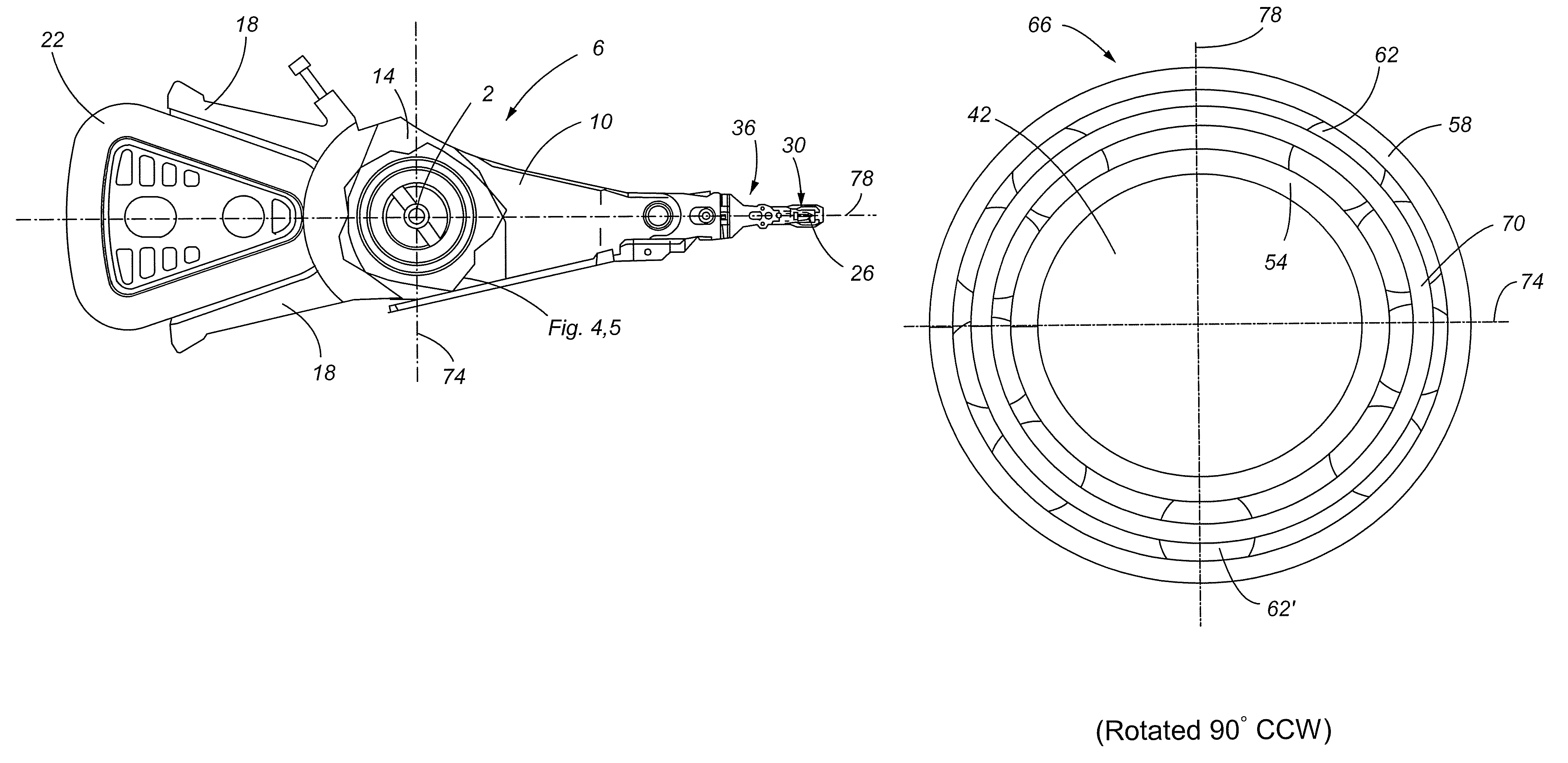
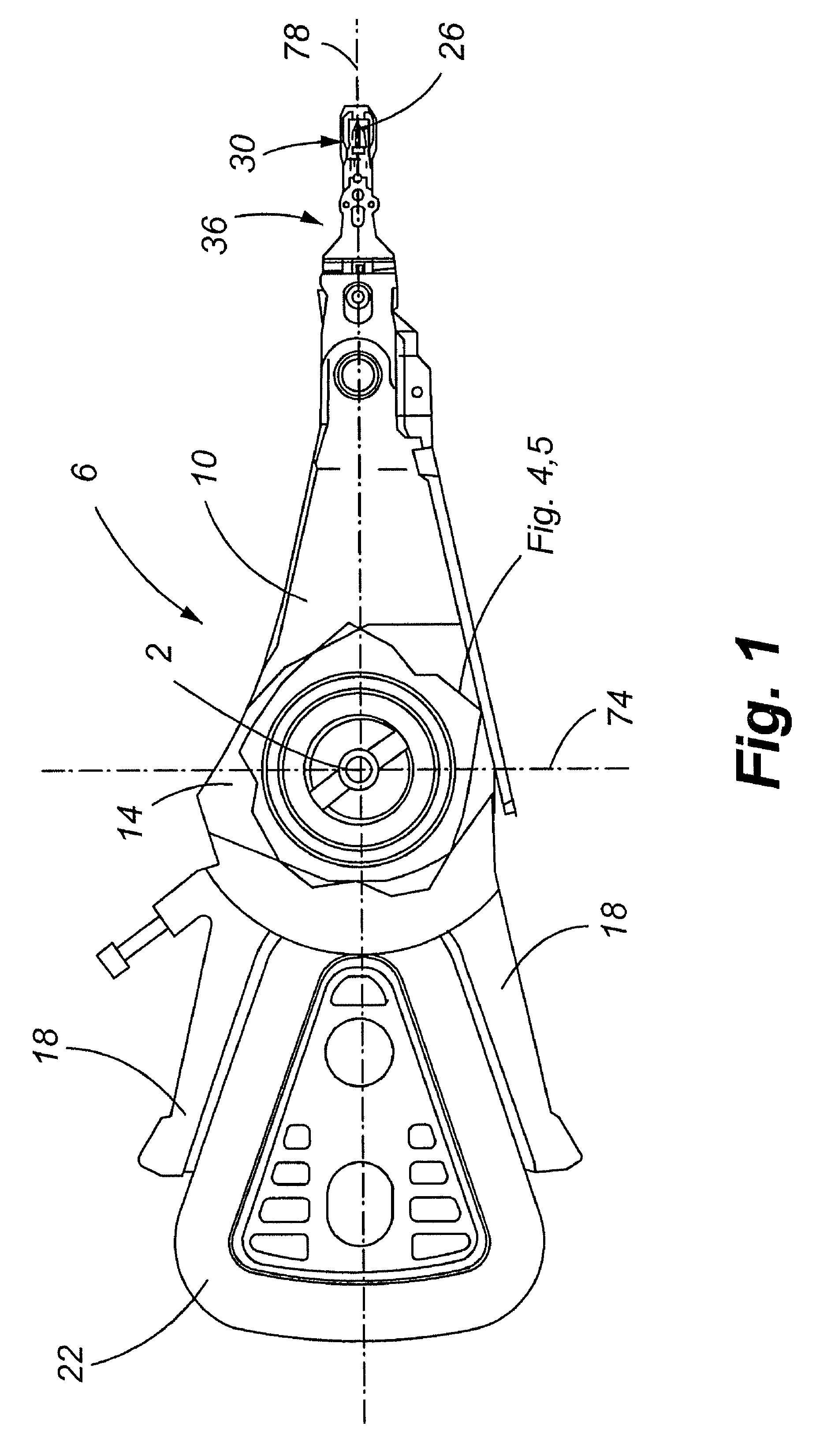
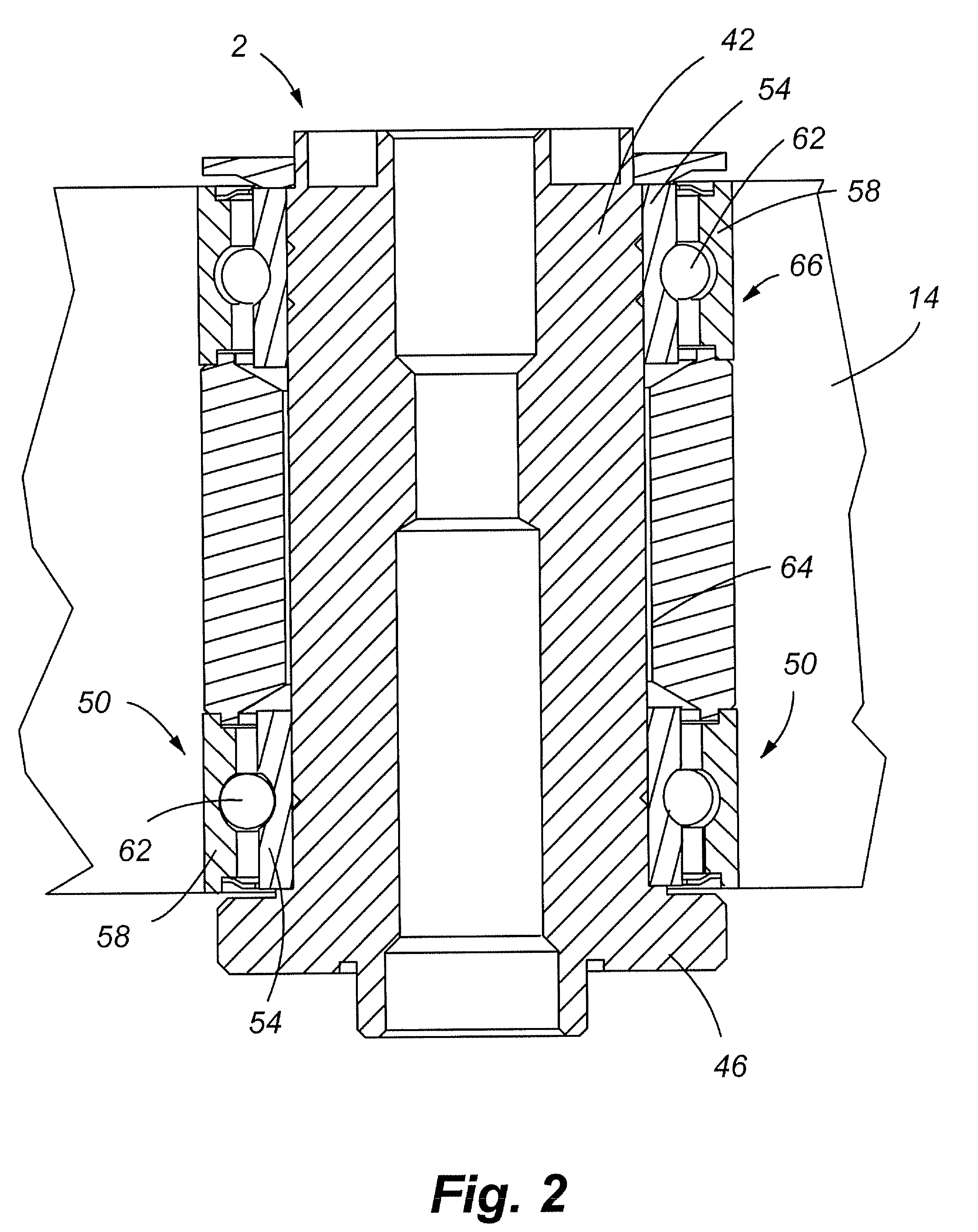
[0033]Referring now to FIGS. 1-10, a pivot bearing cartridge 2 for an actuator assembly 6 is shown. More specifically, an actuator assembly 6 of a disk drive includes a plurality of actuator arms 10 that are interconnected to a centralized E-block 14. Two members 18 are also included, positioned opposite the actuator arms 10, that provide a location or yoke for interconnection of a voice coil 22. The E-block 14 includes an aperture therethrough for the receipt of a pivot assembly 2 that allows the actuator assembly 6 to freely rotate about a fixed shaft 42 (FIG. 2) when electromagnetic attractive and repulsive forces interact with the voice coil 22. The rotation of the actuator assembly 6 places a transducer or read / write element 26 over preselected areas of a rotating disk to read and / or write data from or to the disk. The read / write element is positioned on a slider 30 which, in turn, is connected to suspension 36 attached to the distal end of the actuator arm 10. Embodiments of t...


PUM

PropertyMeasurementUnit
cage rotationaaaaaaaaaa
stiffnessaaaaaaaaaa
resonance frequencyaaaaaaaaaa

Abstract

A method is provided for maintaining the aggregate stiffness of a pivot bearing assembly generally employed along with an actuator assembly of a magnetic disk drive, while increasing the stiffness in a predetermined direction. More specifically, bearing cartridges used in conjunction with actuator assemblies of the prior art employ at least one ball bearing assembly positioned about a stationary shaft. A modification is presented herein that generally concerns repositioning and maintaining the balls of the ball bearing along a predetermined axis for efficient reaction of loads.

Description

CROSS-REFERENCE TO RELATED APPLICATIONS[0001]This application claims the benefit of U.S. Provisional Patent Application Ser. No. 60 / 747,564, filed May 18, 2006, which is incorporated by reference in its entirety herein.FIELD OF THE INVENTION[0002]The present invention relates to a hard disk drive having improved seek performance. More specifically, the present invention relates to customizing the cartridge assembly stiffness of a disk drive actuator assembly by increasing radial stiffness in at least one direction and decreasing the radial stiffness in a less critical direction.BACKGROUND OF THE INVENTION[0003]Hard disk drives store information on magnetic disks. Typically, the information is stored on concentric tracks of the disk that are divided into servo sectors and data sectors. Information is written to or read from the disk by a transducer or head, mounted on an actuator arm that positions the transducer over the disk in a predetermined location. Accordingly, the movement of...

Claims


Application Information

Patent Timeline
Patent Type & Authority Patents(United States)
IPC IPC(8): G11B5/55
CPCG11B5/5526
Inventor FISHER, FREEMANWOODS, GERRY
Owner SEAGATE TECH LLC
Learn More