Wireless detonator assemblies, and corresponding networks

a technology of detonator and wire, which is applied in the direction of lighting and heating equipment, combustion process, weapons, etc., can solve the problems of large labor cost, many faults, and the wire itself becoming a nuisan

Active Publication Date: 2011-04-19
ORICA EXPLOSIVES TECH PTY LTD
View PDF9 Cites 90 Cited by
  • Summary
  • Abstract
  • Description
  • Claims
  • Application Information

AI Technical Summary

Problems solved by technology

This process causes significant labour costs and generates many of the faults that occur due to failed or damaged connections.
Moreover, the wire itself becomes a nuisance.
Firstly it prevents easy movement of men and vehicles over the blasting site and is itself easily damaged.
Secondly it has to be gathered for disposal being unfit for reuse or it becomes an undesirable material contaminant of the ore body being extracted.
However, such systems present formidable technological challenges, many of which remain unresolved.
One obstacle to automation is the difficulty of robotic manipulation and handling of detonators at the blast site, particularly where the detonators require tieing-in or other forms of hook up to electrical wires, shock tubes or the like.
In addition, manual set up and tieing in of detonators via physical connections is very labour intensive, requiring significant time of blast operator time.
Nonetheless, existing wireless blasting systems still present significant safety concerns, and improvements are required if wireless systems are to become a viable alternative to traditional “wired” blasting systems.

Method used


Image

  • Wireless detonator assemblies, and corresponding networks
  • Wireless detonator assemblies, and corresponding networks
  • Wireless detonator assemblies, and corresponding networks

Examples


example 1

Discussion of Preferred Logging Device / Top-Box Configurations

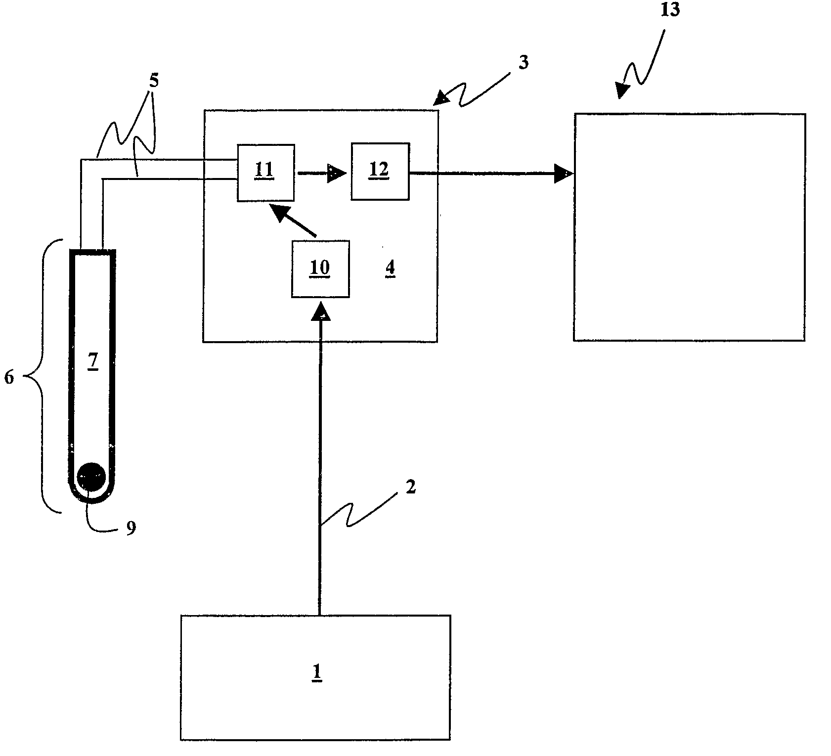
[0086]In selected embodiments, the blasting apparatus of the present invention may include a logging device for individually programming each wireless detonator assembly. For example, a logging device may instruct the top-box of each wireless detonator assembly, to ascertain the EDD's identity or serial number and in doing so, verify that the communications between top-box and EDD are functioning. The logger may then record information such as the top-box identity number and some location information optionally required for the blasting application.

[0087]For logging, the logging device preferably communicates with the top-box in a manner such that there is virtually no possibility that another top-box and associated detonator in the system “overhears” the communication and improperly processes or transmits data to or from the logging device. For example, a logging device may only communicate with a top-box if within very c...

example 2

Compensation for Signal Transmission Delays at Intermediary Nodes of a Network of Wireless Detonator Assemblies

[0104]In an “self organizing” network of the present invention, the time for a message to get from master (e.g. a blasting machine) to slave (e.g. one or more wireless detonator assemblies) will vary between nodes of the network (i.e. wireless detonator assemblies acting to relay wireless signals to other nodes in the network). Preferred features of the self-organizing network of the present invention allow for compensation of these variable times. To allow for the time variation for critical messages, the inventors propose the following scheme. Any message that requires synchronism is sent out with a sufficiently large advance time offset, X, so that it says “In time X from now, start the action!”. Any device relaying that message may then deduct its own message processing and sending time from X so that eventually when all nodes on the network have received it they all ac...

example 3

Network Communications and Relay Delay Compensation

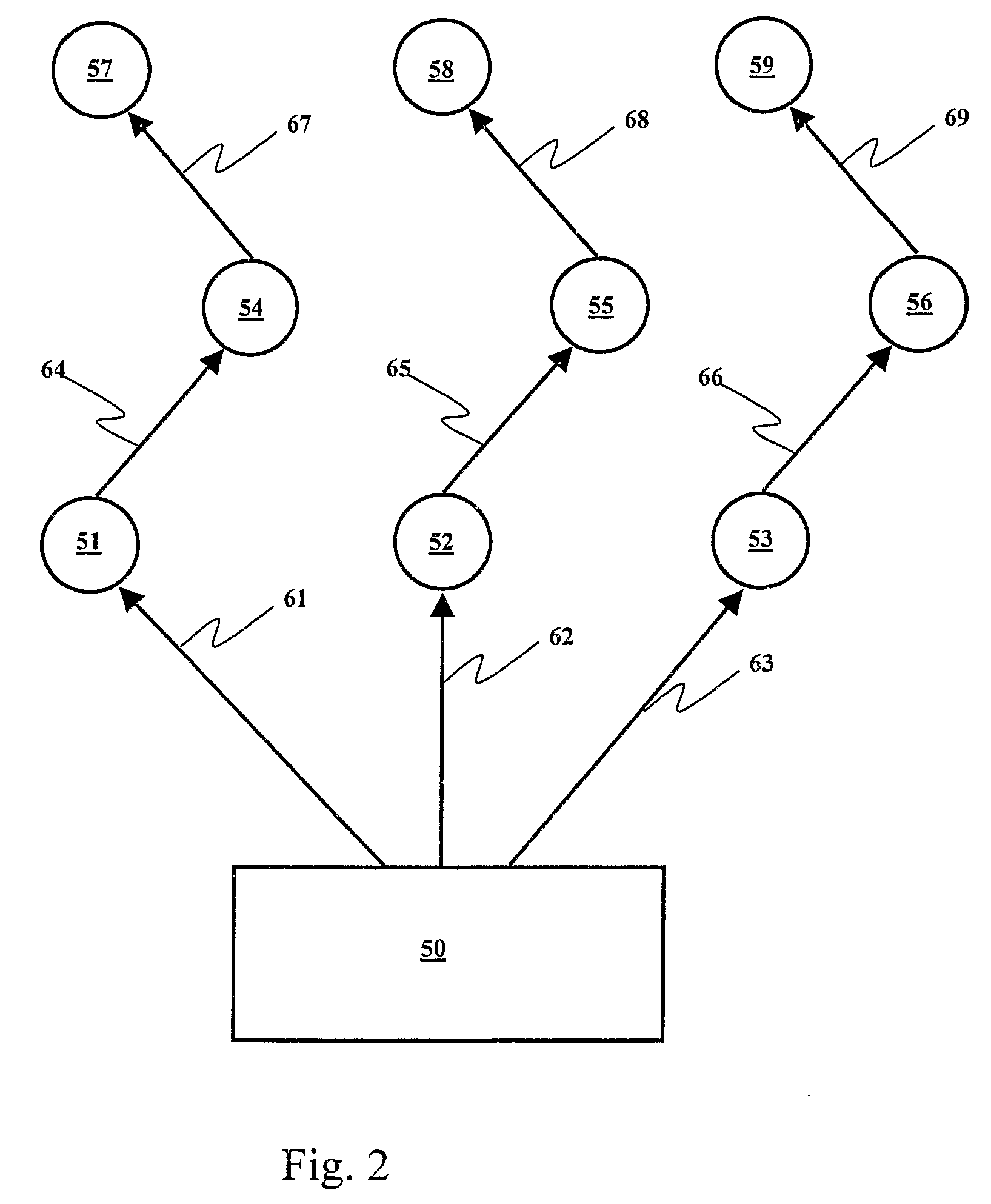
[0106]A number of radio frequency (RF) receiver / transmitter (TX / RX) devices, with attached microprocessors (computers) can organize themselves into communication networks which provide reliability by using multiple paths and achieve network repair, when one of them is damaged, removed or added, by making adjustments to the message passing rules.

[0107]The operation of such networks generally employs collision avoidance means in which the RF TX / RX device first listens on the assigned frequency to see if any other device is transmitting and if the channel is clear, starts its own transmission. If not clear then it may wait for a (random) time before trying again. This naturally introduces unpredictable delays in the system, especially if any device on the network may decide at any time to send its own message to another (in peer to peer communications), thus temporarily blocking others. This problem is likely to be less severe in a mas...


PUM


Abstract

Wireless detonator assemblies (51-59) in use, form a cross-communicating network of wireless “detonator assemblies, such that communication of each wireless detonator assembly (57-59) with an associated blasting machine (50) can occur either directly, or via relay of signals (61-69) between other wireless detonator assemblies (51-56) in the network. Wireless detonator assemblies (51-59) can disseminate information (such as status information, identity information, firing codes, delay times and environmental conditions) among all of the wireless detonator assemblies in the network, while compensating for signal transmission relay delays at nodes in the network, thereby enabling the wireless detonator assemblies to detonate the explosive charges in accordance with the delay times. Various wireless detonator assemblies and corresponding blasting apparatus are disclosed and claimed. Methods of blasting using the wireless detonator assemblies and blasting apparatus are also disclosed and claimed.

Description

[0001]This application is the National Phase of PCT International application No. PCT / AU2006 / 000085 filed on Jan. 24, 2006 which claims priority under 35 U.S.C. 119(e) on U.S. Provisional Application No(s). 60 / 646,312 filed on Jan. 24, 2005. The entire contents of the prior application are hereby expressly incorporated by reference into the present application.FIELD OF THE INVENTION[0002]The present invention relates to the field of wireless detonator assemblies, their organization into a network, and their timed actuation at a blast site.BACKGROUND TO THE INVENTION[0003]The operation of electronically timed detonators, also known as electronic delay detonators, or EDDs, for blasting, mining, quarrying and similar operations is conventionally performed by use of a network or harness of wires that connect all the detonators together and to the devices that control them. Typically, each detonator is located below ground in the bulk of the explosive material, with a connection made to ...

Claims


Application Information

Patent Timeline
Patent Type & Authority Patents(United States)
IPC IPC(8): F23Q7/00
CPCF42D3/04F42D1/055
Inventor HUMMEL, DIRKMCCANN, MICHAEL JOHN
Owner ORICA EXPLOSIVES TECH PTY LTD
Why Eureka
Try Eureka