Method of installing an interlocking floor system

a floor system and interlocking technology, applied in the field of floor coverings, can solve the problems of difficult removal and high installation cost of base materials, and achieve the effects of reducing high area, removing vegetation from an area, and filling low area

Active Publication Date: 2011-04-26
CH3 SOLUTIONS LLC
View PDF12 Cites 26 Cited by
  • Summary
  • Abstract
  • Description
  • Claims
  • Application Information

AI Technical Summary

Benefits of technology

In another embodiment, a method of installing an interlocked floor system is disclosed including providing polymeric panels are disclosed including a rigid integral body having a planar top surface and a grid structure supporting the top surface and multiple interlocking side surfaces. Each interlocking side surface has upwardly and downwardly facing steps with the downwardly facing steps having a convex projection on a bottom surface and the upwardly facing steps having a concave mating dimple on an upper surface. An over hang ledge is formed as an extension of the planar top surface, thereby forming a cavity between the over hang ledge and the upper surface of the upwardly facing step. An under hang ledge is formed in a top surface of the downwardly facing steps allowing the downward facing steps of a first panel to fit within the cavity of a second panel. The steps of the side surfaces of the first panel interlock to complementary steps of the second panel. The method continues with eliminating vegetation from an area, filling low areas and reducing high areas of the area and compacting the surface of the area. Next, a cover material is installed over the surface of the area. The multiple polymeric panels are then joined together and placed over the cover material.

Problems solved by technology

These base materials are expensive to install, and once installed are difficult to remove.

Method used


Image

  • Method of installing an interlocking floor system
  • Method of installing an interlocking floor system
  • Method of installing an interlocking floor system

Examples


Embodiment Construction

Throughout the following detailed description the same reference numerals refer to the same elements in all figures.

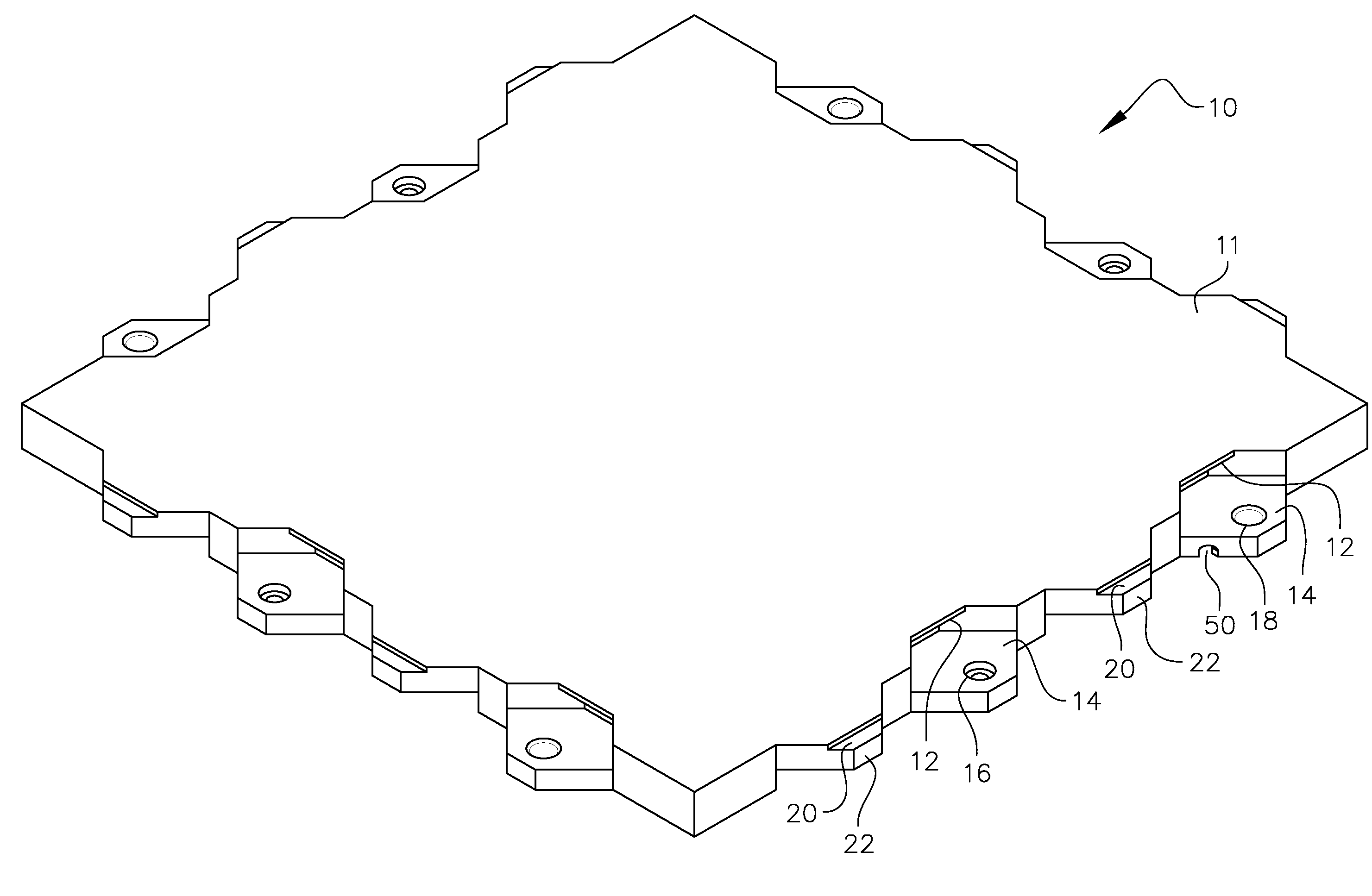
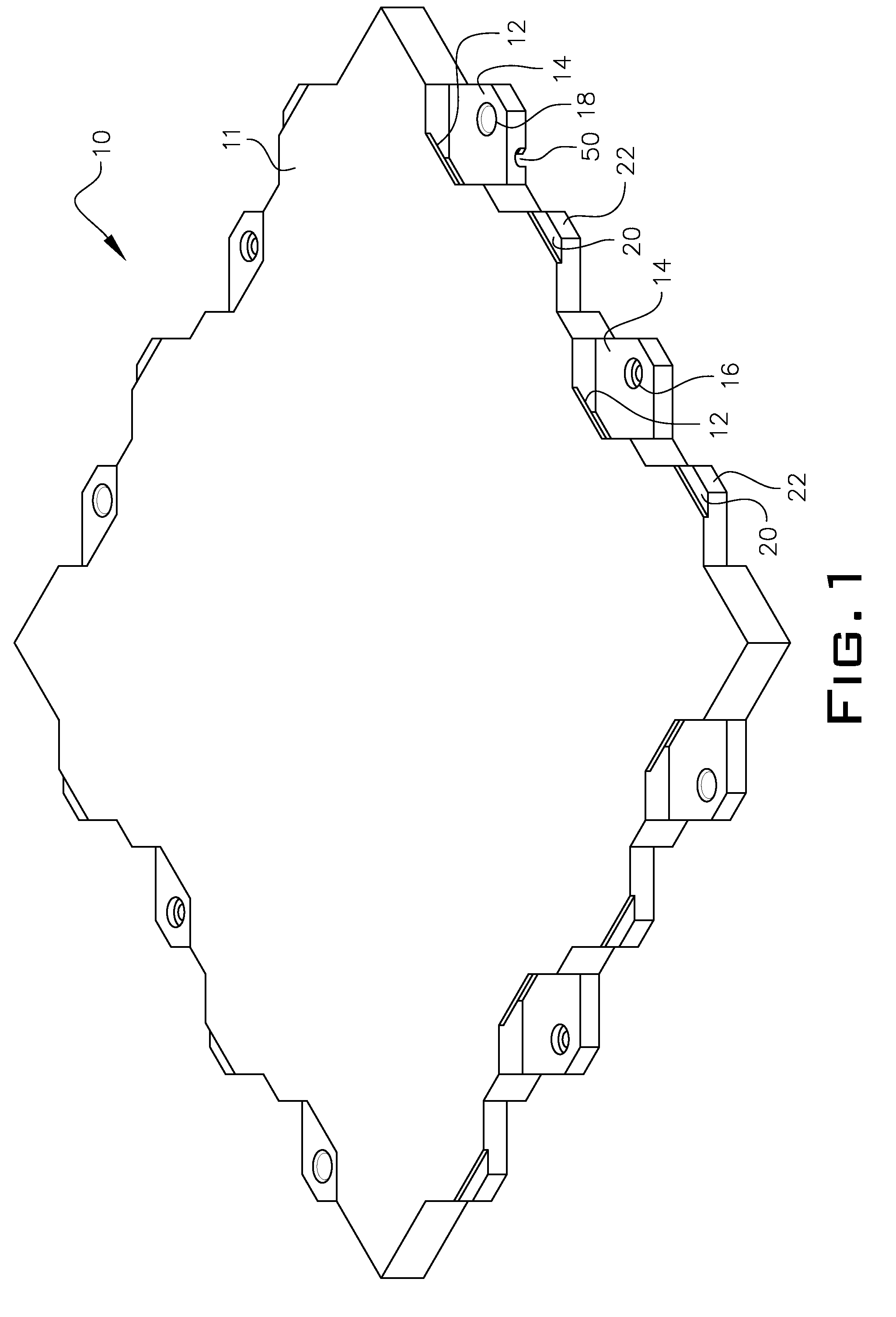
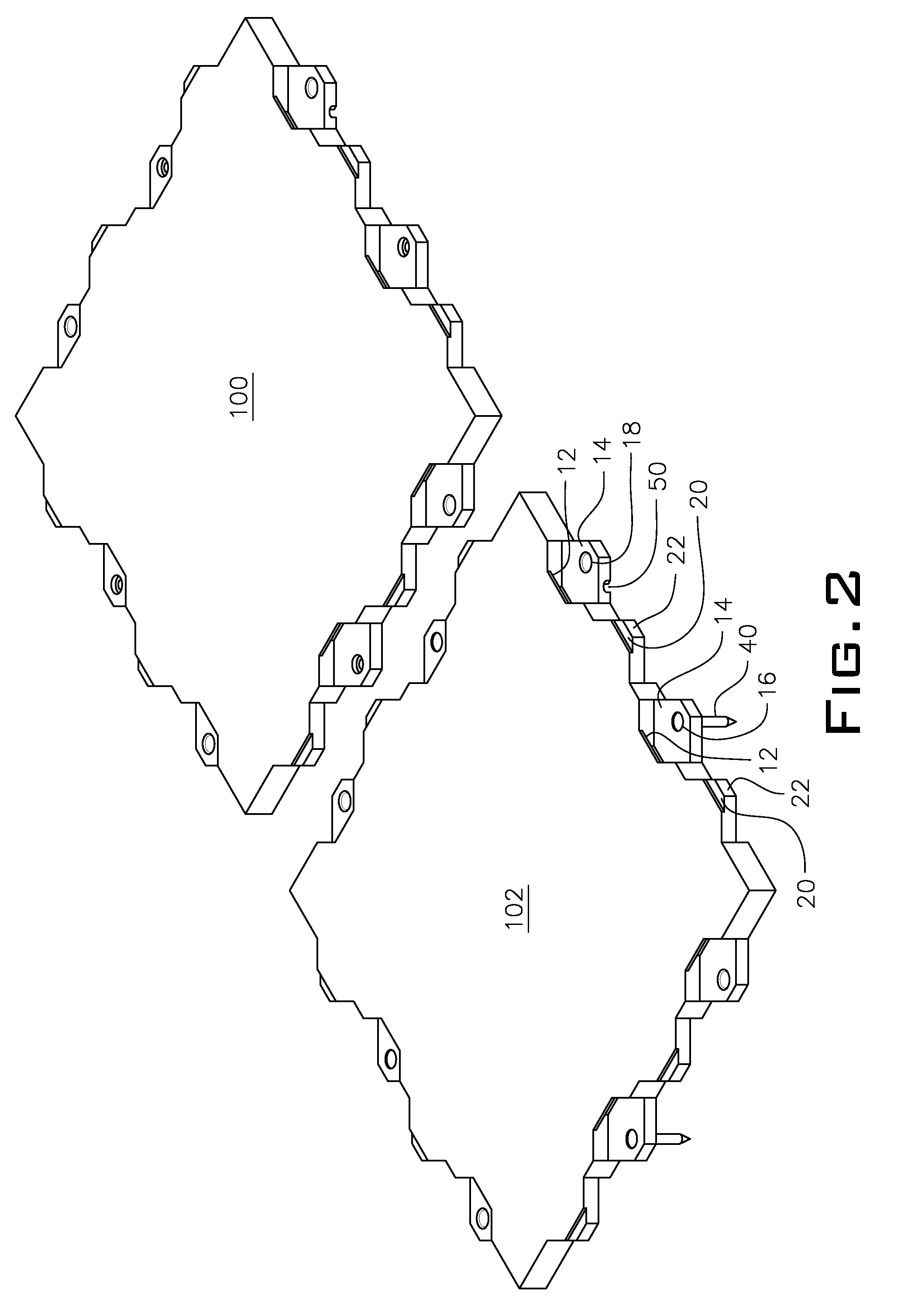
Referring to FIGS. 1, 2, 8 and 8A, panels 100 / 102 join together to form an interlocked series of panels arranged to be mechanically interlocked together. Each panel 10 has a planar top surface 11 and each panel 10 has upward facing steps 14 and downward facing steps 22. At least one of the downward facing steps 22 contains a downwardly pointing convex projection 24 on their lower surfaces as shown in FIG. 8. At least one of the upward facing steps 14 contains a concave mating dimple 18 on their upper surface. An under hang ledge 20 is provided to allow the downward facing steps 22 to be inserted with the under hang ledge 20 sliding into a cavity formed between the upward facing steps 14 and an overhang ledge 12, thereby engaging the convex projections 24 with concave dimples 18. The overhang ledge is a continuation of the planar top surface 11 of the panel 10. Such an ...


PUM

PropertyMeasurementUnit
areasaaaaaaaaaa
areaaaaaaaaaaa
polymericaaaaaaaaaa

Abstract

A method of installing an interlocking floor system includes surface preparation, assembly of the polymeric panels making up the interlocking floor system and affixing a turf material over the polymeric panels.

Description

FIELD OF THE INVENTIONThe present invention relates to flooring. More particularly, it refers to the installation of multi-sectional interlocking polymeric panels held together by a mechanical locking feature, the panels forming a floor surface or under laying surface.BACKGROUND OF THE INVENTIONSurface coverings, such as carpet, linoleum, wood flooring, rubberized flooring system, and tile, need to be laid over a base that will support the surface covering. Commonly, surface coverings are laid over a base of plywood or cement. These base materials are expensive to install, and once installed are difficult to remove. Recreational surfaces frequently need to be moved to different locations because the same site may be used for different activities, such as an ice rink converted to a basketball court or concert stage. A need exists for an inexpensive, easily movable base surface as a stand-alone floor surface or for use in conjunction with multiple surface coverings.US Pub. No. 2005-00...

Claims


Application Information

Patent Timeline
Patent Type & Authority Patents(United States)
IPC IPC(8): E04B2/00E04F15/00
CPCB44C1/28B44C5/0461E04F15/10Y10T428/24777E04F2201/091E04F2201/095E04F15/02194E04F15/043E04F15/087E04F15/105
Inventor BARLOW, DAVID R.
Owner CH3 SOLUTIONS LLC
Why Eureka
Try Eureka