Mass spectrometer with looped ion path

a mass spectrometer and looped ion technology, applied in the field of mass spectrometers, can solve the problems of ineffective extension of the approach to higher orders of msn, complex mass spectrometers of this description, and significant compromise of instrument sensitivity and minimum detection levels

Inactive Publication Date: 2011-04-26
THERMO FINNIGAN
View PDF30 Cites 16 Cited by
  • Summary
  • Abstract
  • Description
  • Claims
  • Application Information

AI Technical Summary

Problems solved by technology

However, a mass spectrometer of this description would be complex, bulky and expensive.
Furthermore, this approach could not be effectively extended to higher orders of MSn (i.e., n≧4), due to the high transmission losses, which would significantly compromise instrument sensitivity and minimum detection levels.
The prior art approaches, while technically feasible, require complex electronics that are difficult to implement reliably, and may otherwise result in instrument design problems or have undesired effects on instrument performance.
Also, in this approach the mass filter and adjacent storage / collision cells are blocked for the entire time of analysis, thus increasing time between scans and potentially aggravating space-charge effects in the pre-storage trap.

Method used


Image

  • Mass spectrometer with looped ion path
  • Mass spectrometer with looped ion path
  • Mass spectrometer with looped ion path

Examples


first embodiment

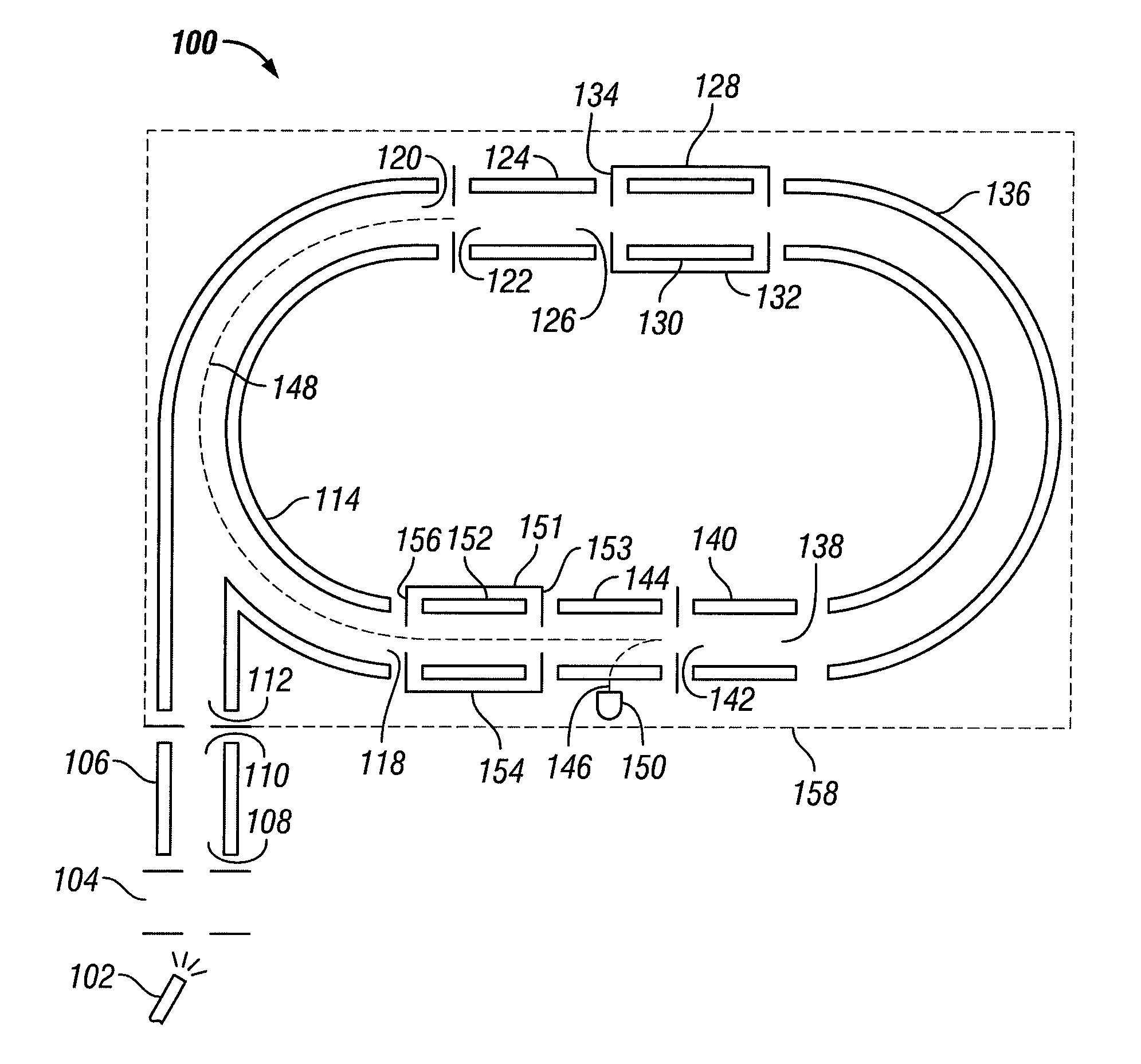
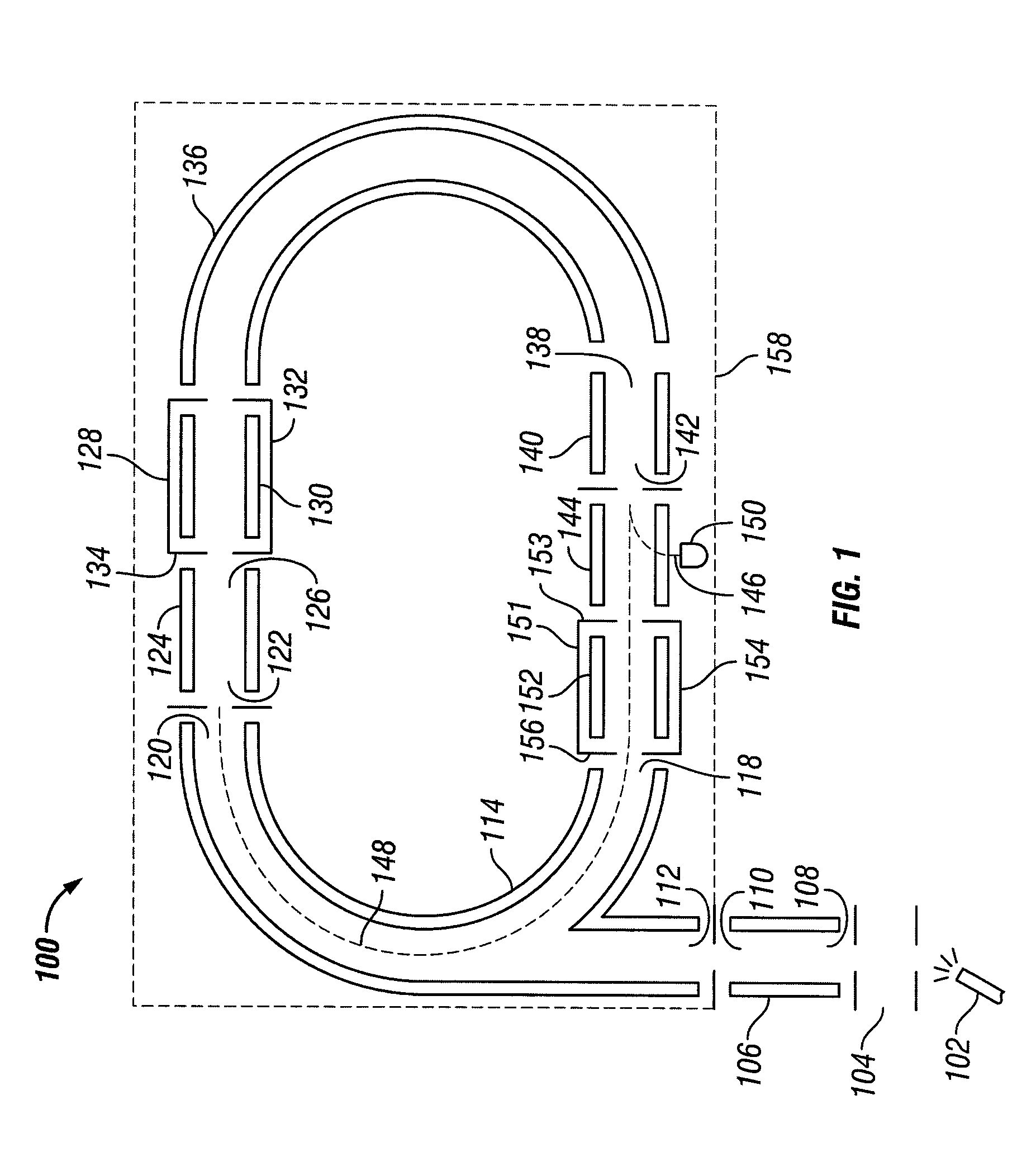
[0017]FIG. 1 shows a mass spectrometer 100 constructed in accordance with the invention. A conventional ion source 102 generates ions from a sample to be analyzed, such as the eluate from a liquid chromatographic column. While an electrospray ionization source is shown as an illustrative example, any other suitable ion source or combination of sources may be employed, including continuous sources such as atmospheric pressure chemical ionization (APCI) and atmospheric pressure photoionization (APPI) sources and pulsed sources such as a matrix assisted laser desorption / ionization (MALDI) source. Ions produced by ion source 102 are transported through an interface region 104, which may include one or more differentially-pumped intermediate chambers of successively lower pressure, and are delivered to an inlet end of ion guide 106. Various ion optics and ion transfer devices, such as electrostatic and RF lenses, ion transfer tubes and ion guides may be disposed within the interface to i...

second embodiment

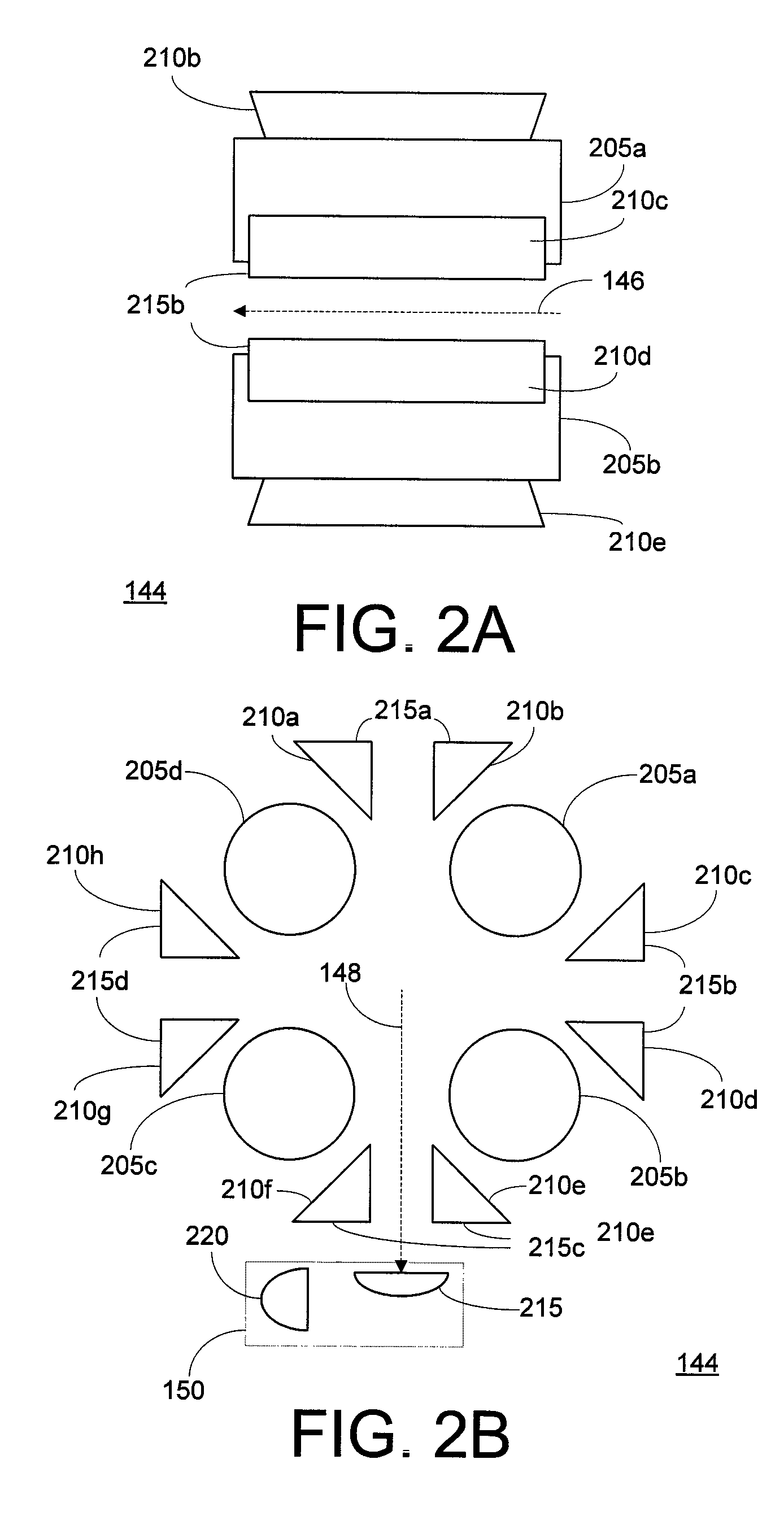
[0027]FIGS. 3A and 3B depict (in side elevational and lateral-cross-sectional views) ion path switching device 144, which takes the form of four generally planar electrodes 305a-d coupled to RF and DC voltage sources (not shown). Electrodes 305a-c may be substantially identical in their construction, while a central portion 310 of electrode 305d is formed from a conductive mesh or is adapted with an array of apertures that define a set of passageways extending through the thickness of electrode 305d. Electrodes 305a-d are arranged into a quadrupole structure comprising two pairs of opposed electrodes. When ion path switching device 144 is to be operated in a transmission mode, oscillatory (e.g., RF) voltages are applied in a prescribed phase relationship to electrodes 305a-d, with one electrode pair receiving a voltage opposite in phase to the other electrode pair. As known in the art, this creates an oscillatory field that radially confines ions, causing the ions to be transported ...


PUM


Abstract

A mass spectrometer includes at least one ion selector, at least one collision cell, and an ion path switching device arranged to define a looped ion path around which ions derived from a sample may be sent multiple times (without reversal of ion travel) in order to effect a desired number of isolation / fragmentation cycles for MSn analysis. When the desired number of isolation / fragmentation cycles have been completed, the ion path switching device directs the ions to a detector or a separate mass analyzer for acquisition of a mass spectrum.

Description

FIELD OF THE INVENTION[0001]The present invention relates generally to mass spectrometers, and more particularly to mass spectrometers capable of performing multiple stages of ion isolation and fragmentation.BACKGROUND OF THE INVENTION[0002]Triple quadrupole mass spectrometry is a well-established and widely used technique for analysis of a variety of substances, including small molecules such as pharmaceuticals and their metabolites, and large molecules such as peptides. Roughly described, a triple quadrupole mass spectrometer consists of two quadrupole mass filters separated by a collision cell. Each of the quadrupole mass filters is constructed from a set of rod electrodes to which oscillatory (e.g., radio-frequency (RF)) and direct current (DC) voltages are applied. The relative magnitudes of the applied RF and DC voltages are varied to adjust the range of mass-to-charge values (m / z's) for which ions are transmitted through the quadrupole mass filter. The collision cell may take...

Claims


Application Information

Patent Timeline
Patent Type & Authority Patents(United States)
IPC IPC(8): B01D59/44
CPCH01J49/062H01J49/0081
Inventor KOVTOUN, VIATCHESLAV V.MAKAROV, ALEXANDER ALEKSEEVICH
Owner THERMO FINNIGAN
Why Eureka
Try Eureka