Rotor for rotating electrical machine

a technology of rotating electrical machines and rotors, which is applied in the direction of rotating parts of magnetic circuits, dynamo-electric machines, and shape/form/construction of magnetic circuits, etc., can solve the problems of significant price increase, and complicated shapes of first and second rotor frames, so as to reduce heat dissipation and energy loss and the effect of reducing the eddy curren

Active Publication Date: 2011-04-26
HONDA MOTOR CO LTD
View PDF7 Cites 2 Cited by
  • Summary
  • Abstract
  • Description
  • Claims
  • Application Information

AI Technical Summary

Benefits of technology

[0010]A first object of the present invention was attained in view of such circumstances, and is to minimize an eddy current generated in a rotor of a rotating electrical machine to reduce heat dissipation and energy loss.
[0011]In addition, a second object of the present invention is to improve mass-productivity of a rotor of a rotating electrical machine to accomplish reduction in cost.

Problems solved by technology

However, in the second rotor, since connection parts of the two rotor frames and opposite ends of the plurality of fixing members are not insulated, an eddy current generated at the time of operation flows in a closed circuit comprised of one rotor frame, a fixing member, the other rotor frame and the other fixing member, giving rise to possibility of significant heat dissipation and energy loss.
Consequently, the shapes of the first and second rotor frames get complicated to give rise to not only a problem that mass-productivity drops to cause a price increase but also a possibility of making fixation of its induction magnetic pole unstable if there is dispersion in dimensions in the axial direction of a plurality of induction magnetic poles to create a clearance between the induction magnetic pole which is short in dimension and the first and second rotor frames.
Moreover, the shapes of the first and second rotor frames get complicated to give rise to not only a problem that mass-productivity drops to cause a price increase but also a possibility of generating significant heat and energy loss since the connection portions between the two rotor frames and the opposite ends of a plurality of induction magnetic pole supporting portions are not insulated so that an eddy current generated at the time of an operation flows in a closed circuit comprised of one rotor frame, a fixing member, the other rotor frame and the other fixing member.

Method used


Image

  • Rotor for rotating electrical machine
  • Rotor for rotating electrical machine
  • Rotor for rotating electrical machine

Examples


first embodiment

[0110]At first, the present invention will be described based on FIG. 1 to 20.

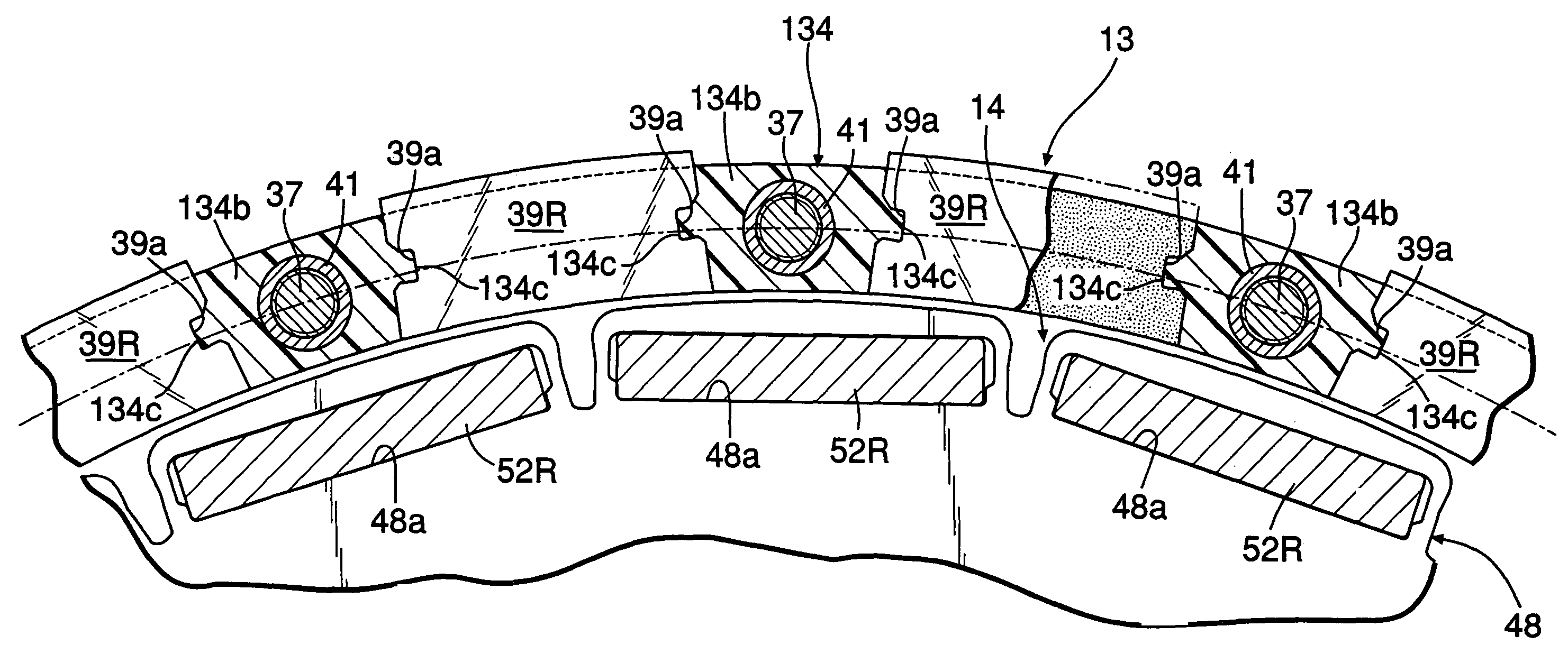
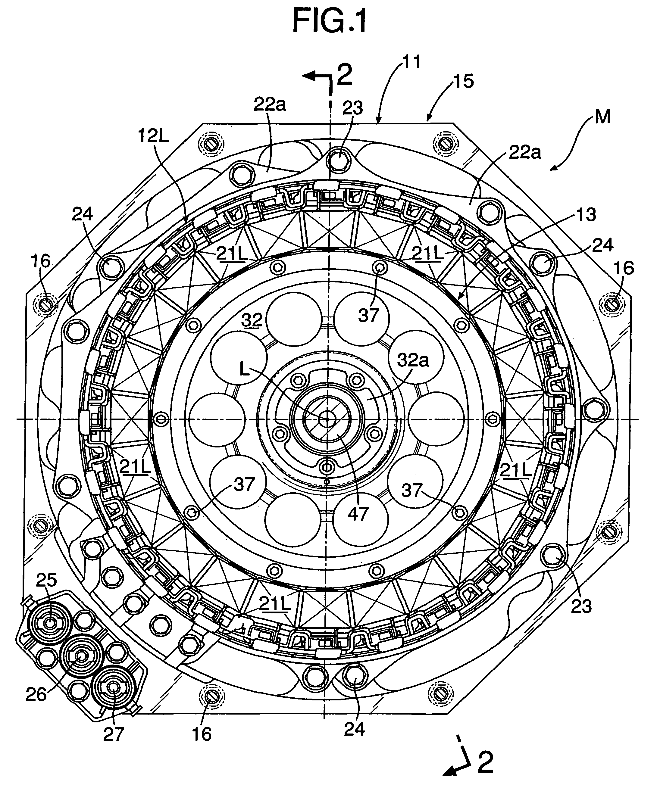
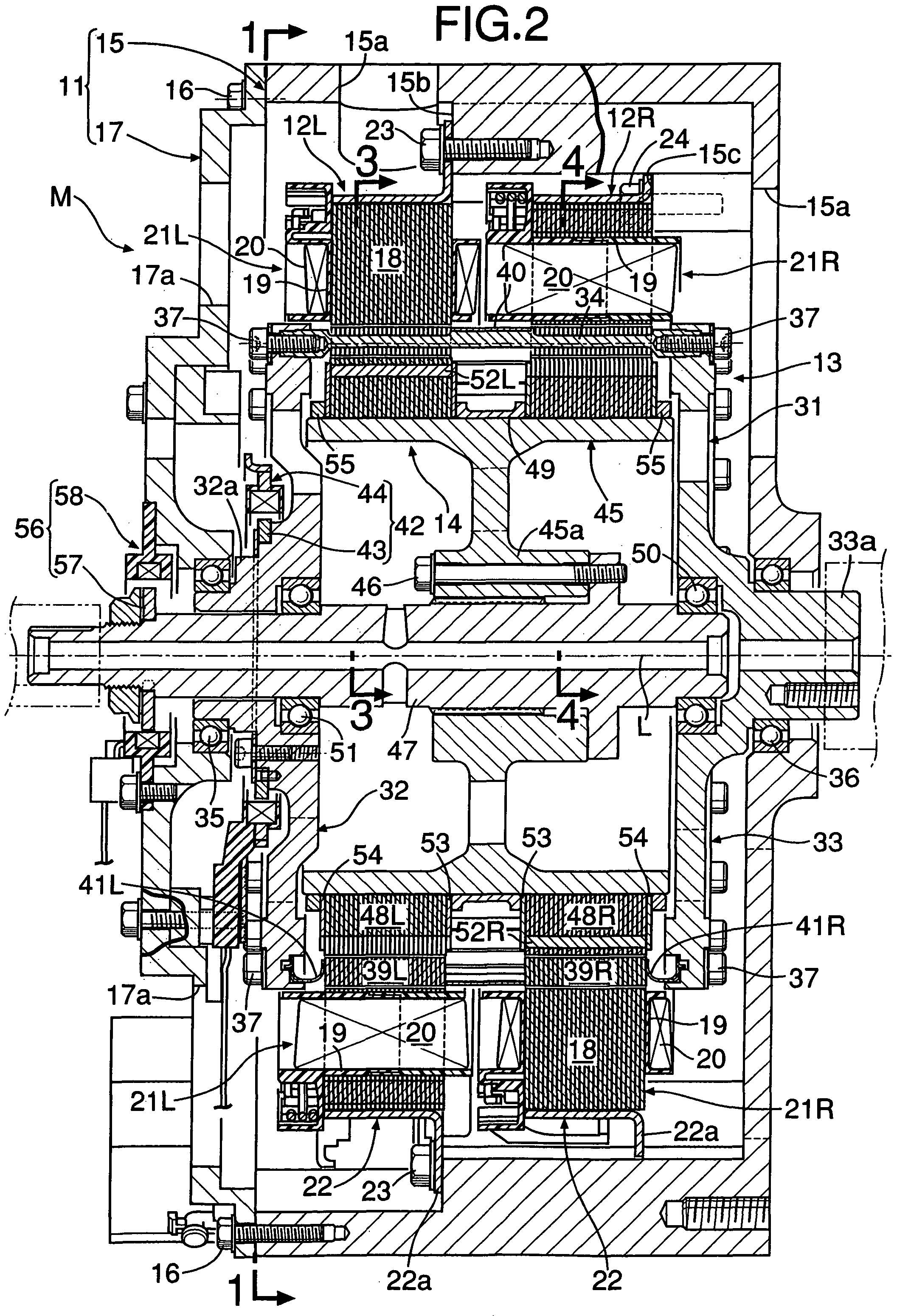
[0111]As shown in FIG. 10, an electric motor M of the embodiment is comprised of a casing 11 comprises an octagonal shape being shorter in the direction of an axis L, circular toroidal first and second stators 12L and 12R fixed in the inner periphery of the casing 11, a cylindrical outer rotor 13 being housed inside the first and second stators 12L and 12R and rotating on the axis L and a cylindrical inner rotor 14 being housed inside the outer rotor 13 and rotating on the axis L. The outer rotor 13 and the inner rotor 14 are relatively rotatable to the first and second fixed stators 12L and 12R and the outer rotor 13 and the inner rotor 14 are mutually relatively rotatable.

[0112]As illustrated in FIG. 1 and FIG. 2, the casing 11 is comprised of a main body part 15 having a bottomed octagonal cylinder shape and a lid portion 17 having an octagonal plate shape being fixed to an opening of the main body part...

second embodiment

[0177]Next, the present invention will be described based on FIG. 21.

[0178]The connection member 34 of the first embodiment is a solid member. However, the connection member 34 of the second embodiment is configured to be hollow by welding two stainless plates, for example, subjected to a press working. That structure lightens the connection member 34 further and reduces its substantial sectional area. Thereby, eddy current can be reduced further.

third embodiment

[0179]Next, the present invention will be described based on FIG. 22.

[0180]In the first embodiment, the first and second flange members 32 and 33 and the connection members 34 are comprised of different members. However, in the third embodiment, a half of the number of the connection members 34 is formed integrally with the first flange member 32. The remaining half thereof is formed integrally with the second flange member 33. The connection members 34 on the side of the first flange member 32 and the connection members 34 on the side of the second flange member 33 are alternately arranged in an assembled state. In that case, the material of the first and second flange members 32 and 33 is a weak magnetic material the same as the material of the connection members 34, that is, aluminum or aluminum alloy.

[0181]Also in that third embodiment, a portion where the connection members 34 on the side of the first flange member 32 are coupled with the second flange member 33 and a portion w...


PUM


Abstract

A rotor body for an electric motor is comprised of connecting outer peripheral portions of first and second flange members made of electrically conductive material to the opposite ends of a plurality of connection members made of electrically conductive material of weak magnetic material arranged at predetermined distances therebetween in the circumferential direction with bolts and by supporting induction magnetic poles made of soft magnetic material between the connection members which are adjacent in the circumferential direction. Coupling portions of the first and second flange members and the connection member are electrically insulated by insulation coating so that an eddy current flowing in a closed circuit comprised of the first flange member, the connection member, the second flange member and the other connection member can be reduced and heat dissipation and energy loss accompanied by the eddy current can be minimized at the time of an operation.

Description

BACKGROUND OF THE INVENTION[0001]1. Field of the Invention[0002]The present invention relates to a rotor for a rotating electrical machine, comprising: a first flange member and a second flange member comprised of an electrically conductive material and arranged so as to face each other on a common axis with a space therebetween; a plurality of connection members comprised of an electrically conductive weak magnetic material and arranged at predetermined distances therebetween in a circumferential direction with the axis being a center; outer peripheral portions of the first flange member and the second flange member being connected together by the connection members to support induction magnetic poles formed of a soft magnetic material between the connection members which are adjacent in the circumferential direction.[0003]In addition, the present invention relates to a rotor for a rotating electrical machine, which is formed of a basket-shape rotating around an axis and supports a...

Claims


Application Information

Patent Timeline
Patent Type & Authority Patents(United States)
IPC IPC(8): H02K21/12
CPCH02K21/029H02K1/276H02K1/30H02K1/22H02K1/27
Inventor BANDO, MASASHIABE, NORIYUKIAKUTSU, SHIGEMITSUOYA, SATOYOSHI
Owner HONDA MOTOR CO LTD
Why Eureka
Try Eureka