Non-contact capacitive sensor and cable with dual layer active shield

a capacitive sensor and active shield technology, applied in the direction of resistance/reactance/impedence, instruments, measurement devices, etc., can solve the problems of generating heat enough to damage the sensor probe and the generator, affecting the accuracy of the expected output, and passing of the electric field signal on the sense plate, so as to reduce the leakage of the electric sense field through these plates , the effect of reducing the eddy curren

Active Publication Date: 2005-12-08
BAKER HUGHES INC
View PDF15 Cites 14 Cited by
  • Summary
  • Abstract
  • Description
  • Claims
  • Application Information

AI Technical Summary

Benefits of technology

[0009] A non-contact capacitive probe has been developed to directly sense the capacitance of the probe relative to a surface or dielectric medium. The capacitive sensor probe has multiple active metallic shield plates that isolate a sense plate and prevent electrical signals from the sense plate from leaking to a ground or potential surface. The sense and active shield plates have grooved surfaces to minimize eddy currents. The grooves of one of the active shield plates is offset and not aligned with the grooves in the other shield plate. By offsetting the grooves in adjacent active shield plates, the leakage of the electric sense field through these plates is substantially reduced or eliminated.

Problems solved by technology

Interaction between the sense signal and any surface except the desired proximate surface of interaction produces an error in the expected output.
These eddy currents, if not curbed, may generate sufficient heat to damage the sensor probe and the generator.
A difficulty is that the electric field signal on the sense plate passes through the combing grooves of the active guard to surfaces that lay behind the active guard.
This leakage current through the guard plate may introduce a measurement error.
Another difficulty created by the combing of the active guard on the sensor and the voids between the metallic conductors of the active-guard layer of the cable is that variations in the combing width and strands may cause inconsistent signal errors from sensor to sensor and cable to cable.
Excessive sensitivity to these variations may increase the difficulty in manufacturing the sensor and increase the sensor sensitivity to temperature and other environmental factors.

Method used


Image

  • Non-contact capacitive sensor and cable with dual layer active shield
  • Non-contact capacitive sensor and cable with dual layer active shield
  • Non-contact capacitive sensor and cable with dual layer active shield

Examples


Embodiment Construction

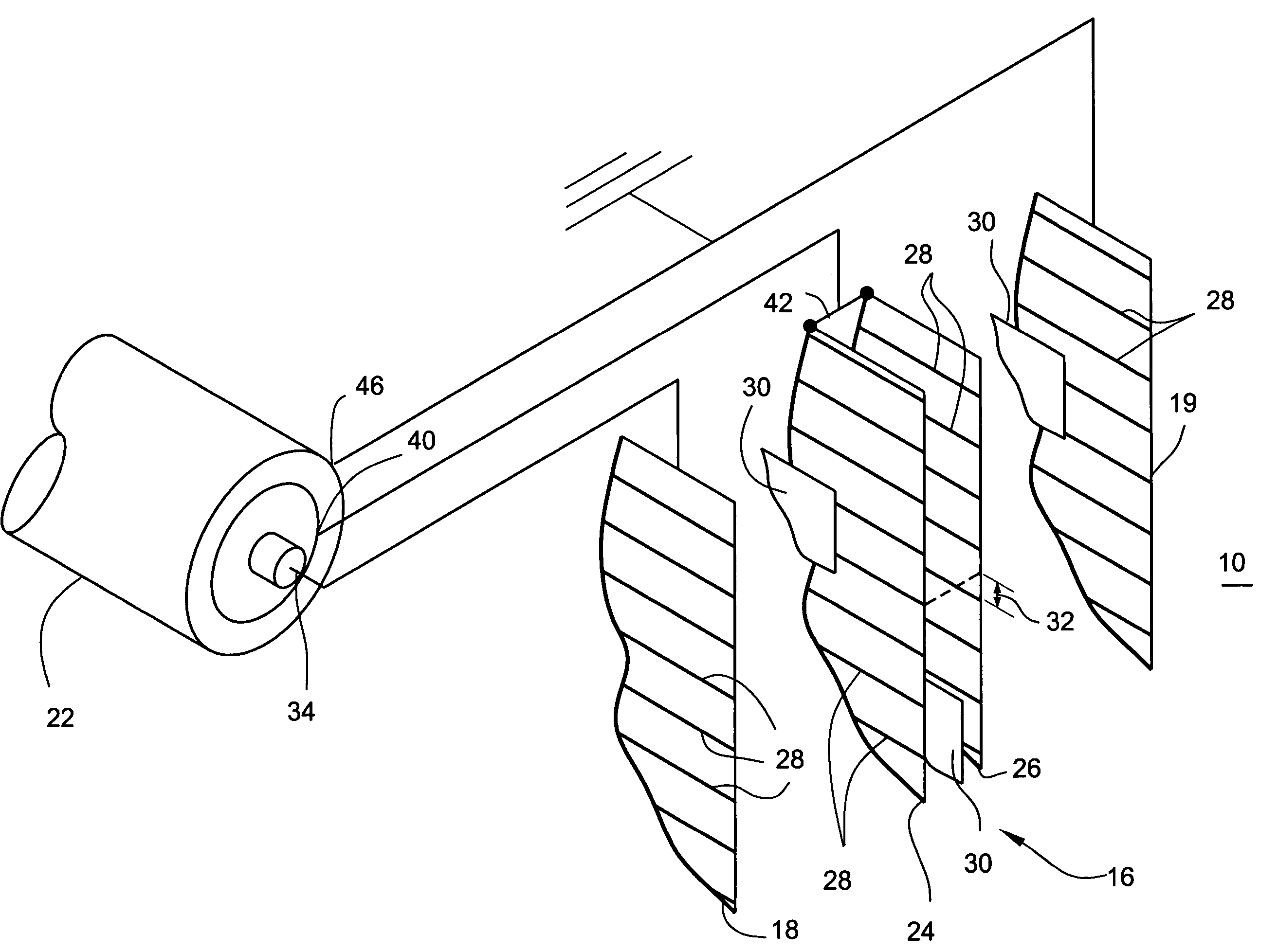
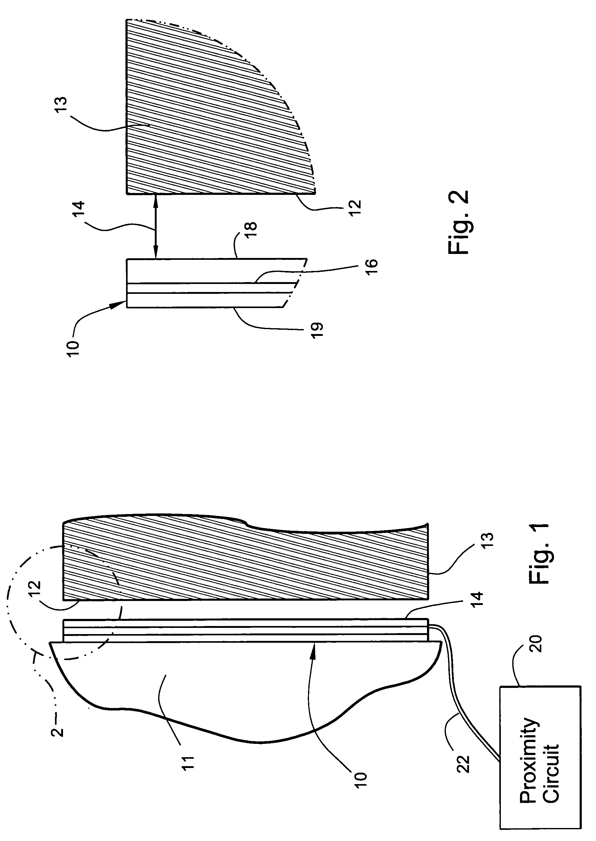
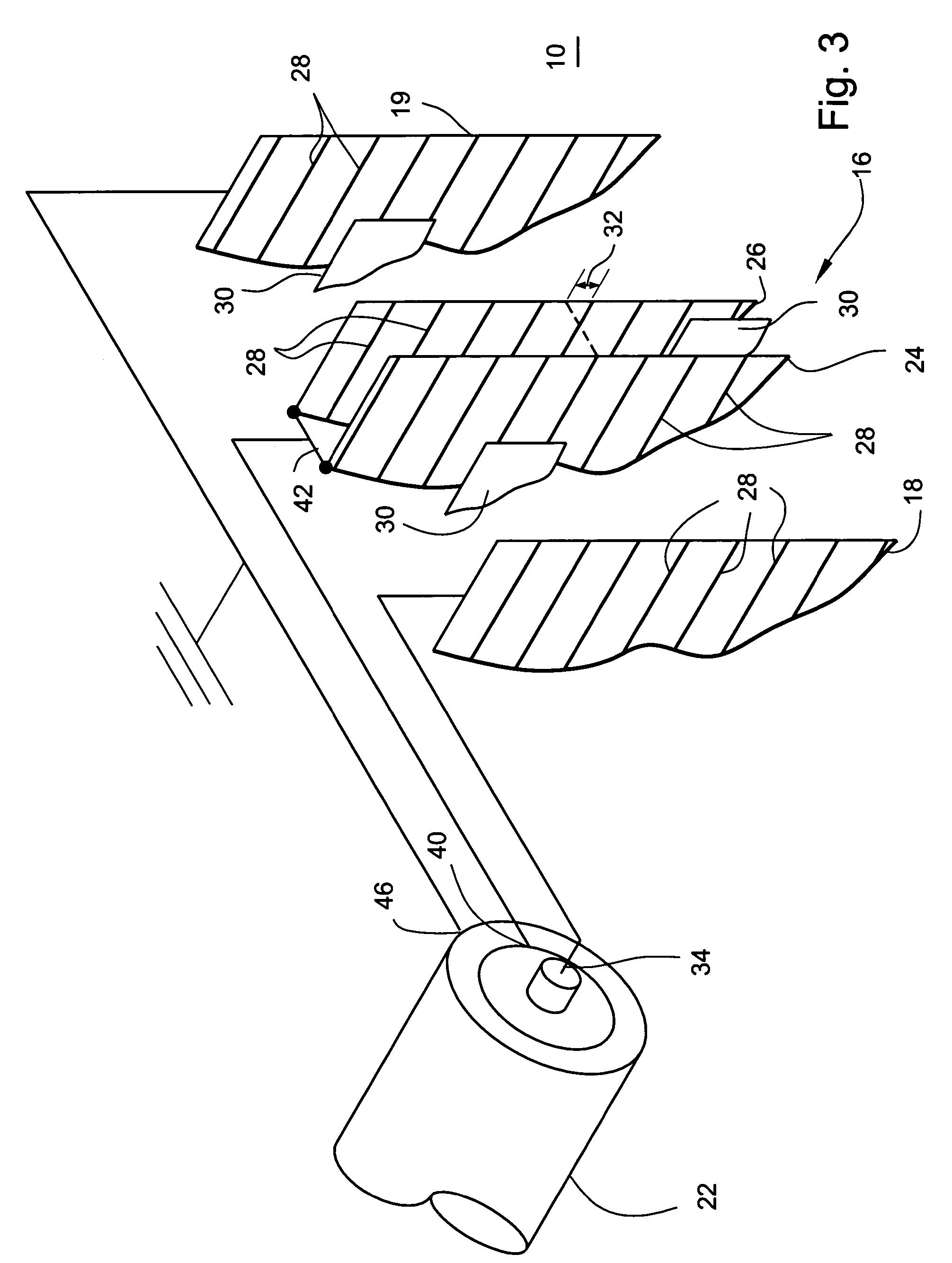
[0018]FIGS. 1 and 2 show schematically a sensor plate probe 10 adjacent an opposite surface 12 and a gap 14 between the sensor and the opposite surface. In one example, the plate probe 10 may be permanently fixed to an inside surface of a stator 11 of a power generator and the opposite surface 12 may be the outer circumference of a rotor of the generator. In this example, the sensor plate probe 10 measures the gap 14 distance between the annular inside stator surface and the cylindrical outer surface of the spinning rotor.

[0019] The sensor probe 10 generates a signal indicative of the distance of the gap 14 or of a proportionality of a dielectric medium in front of the sensor. In addition to measuring a distance of a gap, the sensor probe may determine a change in a dielectric of a fluid flowing in front of the sensor, or the thickness of a material.

[0020] The sensor probe 10 comprises several adjacent conductive plates 16, 18 and 19 that are electrically isolated from each other....


PUM


Abstract

A non-contact capacitive sensor probe including a metallic sensor having a first surface opposite a dielectric medium to be sensed; a plurality of active metallic shields adjacent to the metallic sensor, each of the active metallic shields having a pattern of grooves inhibiting eddy currents on a surface of the shield, wherein the pattern on one shield does not overlap with the pattern on a second shield, and a passive metallic shield adjacent the active metallic shields, such that active metallic shields are sandwiched between the metallic sensor and the passive metallic shield.

Description

BACKGROUND OF THE INVENTION [0001] This invention relates to a method and system for non-contact measurement of a gap between a sensor and a conductive or non-conductive surface using a capacitive measurement device with a plurality of conductive plates that also permits measurement of gas, material depth and dielectric changes in solids and fluids. [0002] Non-contact gap measurement sensors having two parallel superimposed conductive plates, which are electrically insulated from one another, are disclosed in, for example, U.S. Pat. Nos. 4,675,670; 5,990,807; 6,075,464 and 6,552,667. A high frequency signal is placed on the first plate (sense plate) of the sensor. By measuring the capacitive interaction between the sense plate and a proximate surface, the sensor generates a signal that is indicative of the gap or dielectric between the sensor and the surface. [0003] An active guard plate is located behind the sense plate to prevent the sense signal from interacting with surfaces tha...

Claims


Application Information

Patent Timeline
Patent Type & Authority Applications(United States)
IPC IPC(8): G01B7/02G01B7/14
CPCG01B7/14G01B7/023
Inventor LIEDER, OLIVER H.HOWARD, JACK E.
Owner BAKER HUGHES INC
Why Eureka
Try Eureka