
Method and system for monitoring performance of a client-server architecture

a client-server and performance monitoring technology, applied in the direction of digital computers, instruments, wireless commuication services, etc., can solve the problem of monitoring performance of clients

Inactive Publication Date: 2011-04-26
TELECOM ITALIA SPA
View PDF10 Cites 230 Cited by
  • Summary
  • Abstract
  • Description
  • Claims
  • Application Information

AI Technical Summary

Benefits of technology

The patent text describes a method and system for monitoring the performance of a client-server architecture by measuring the time it takes for a server to execute a request and the time it takes for the request to reach the end-user. This is done by using an agent component installed in the server-side portion of the architecture, which emulates requests of actual clients and measures the server execution time and the hit e2e response time. The system can also extract entries from a log file to determine the network delay introduced by the network. The technical effect of this invention is that it allows for non-intrusive monitoring of server performance without changing the server component software.

Problems solved by technology

Applicant has observed that a problem exists of monitoring performance of a client-server architecture (for example in terms of server execution time and end to end response time) by distinguishing network-related problems from server-related problems or even from client-related problems.
Applicant has further observed that another problem exists of monitoring performance of a client-sever architecture by avoiding:installation of client-side agent;modification in the code of end-user requests; andaddition of network traffic.

Method used


Image

  • Method and system for monitoring performance of a client-server architecture
  • Method and system for monitoring performance of a client-server architecture
  • Method and system for monitoring performance of a client-server architecture

Examples


Embodiment Construction

[0056]The following description sets forth numerous implementation-specific details of a monitoring system and associated method. These details are provided in order to illustrate a preferred embodiment of the invention, and do not limit the scope of the invention.

[0057]Throughout this description, it will be assumed that the transactional server being monitored is a web-based system that is accessible via the Internet. It will be recognized, however, that the inventive method can also be used to monitor other types of transactional servers, including those that use proprietary protocols or are accessible only to internal users of a particular organization.

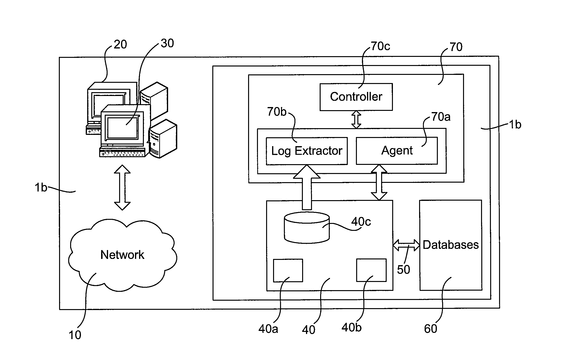
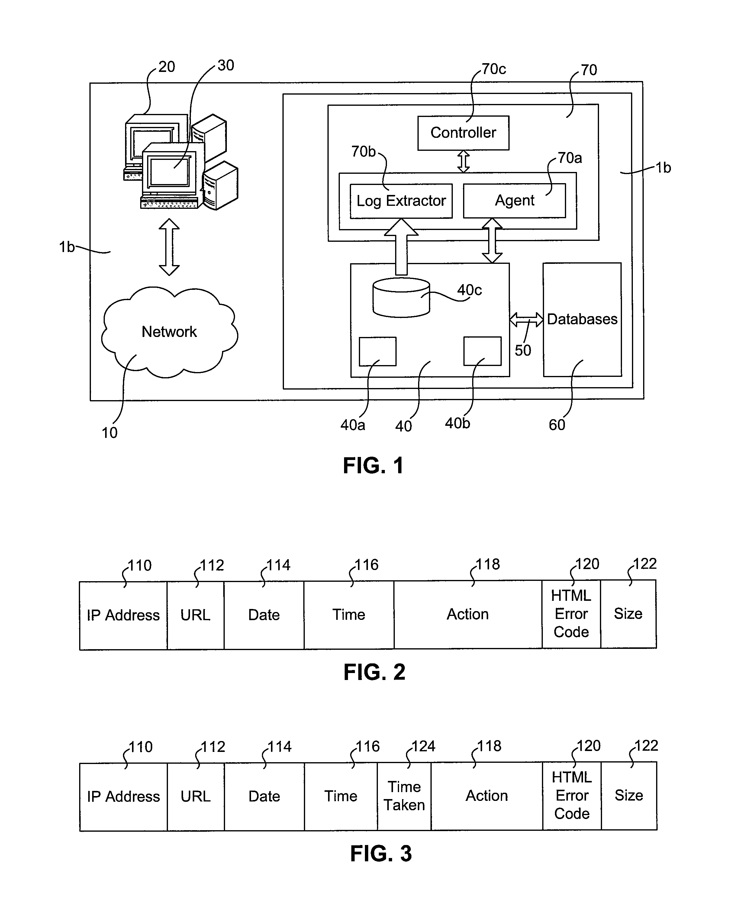
[0058]FIG. 1 shows an exemplary embodiment of a client-server architecture 1 including a client-side portion 1a and a server-side portion 1b connected together via a first network 10, i.e. the Internet.

[0059]The client-side portion 1a comprises at least one, typically a plurality of end-user terminals 20, such as for example perso...


PUM


Abstract

An arrangement which jointly exploits an agent component installed in a server-side portion of client-server architecture for emulating requests of actual clients of the client-server architecture and measuring a server execution time indicative of a time elapsed between reception of an emulated end-user request at a server component and generation of a result of said emulated end-user request at said server component; information stored in a server log file about a hit end to end response time, i.e., the time elapsed between the instant in which the end-user sends a request to the server component and the instant in which result of the request reaches the end-user. From the server execution time and the hit response time, the delay due to the network connecting the server-side portion of the client-server architecture to a client-side portion may be determined. The network delay and the server execution time are then used for monitoring performance of the client-server architecture by distinguishing network related problems from server-related problems or even from client-related problems.

Description

CROSS REFERENCE TO RELATED APPLICATION[0001]This application is a national phase application based on PCT / EP2004 / 011868, filed Oct. 20, 2004, the content of which is incorporated herein by reference.FIELD OF THE INVENTION[0002]The invention relates to techniques for monitoring performance of a client-server architecture. More particularly, the present invention relates to a method and system for monitoring the operation of a client-server architecture including a web-based or other transactional servers.DESCRIPTION OF THE RELATED ART[0003]Different approaches exist for assisting companies in testing the performance and functionality of their web-based transactional servers and associated applications.[0004]Document US 2003-0131052 describes a method, system, apparatus, and computer program product for collecting time-on-page statistics. When a server receives a request for a Web page, the server generates or retrieves the Web page and then instruments the Web page to collect time-on...

Claims


Application Information

Patent Timeline
Patent Type & Authority Patents(United States)
IPC IPC(8): G06F15/173H04W4/00
CPCG06F11/3419H04L41/5009H04L67/34H04L67/125H04L43/0858G06F11/3476G06F2201/875H04L41/5003G06F2201/87H04L43/16H04L67/025
Inventor NASUTO, ANTONIOCASSONE, GIUSEPPEGOTTA, DANILO
Owner TELECOM ITALIA SPA
Learn More