
Device for providing spongy bone with bone substitute and/or bone reinforcing material, bone substitute and/or bone reinforcing material and method

a technology of bone substitute and bone reinforcement, which is applied in the field of devices for providing spongy bone with bone substitute and/or bone reinforcement materials, can solve the problems of poor oxygenation, reduced blood pressure, and obvious risk of tissue material, e.g. blood and fat, in the vertebrae being pressed out into blood vessels or into adjacent tissue,

Inactive Publication Date: 2011-05-03
TEG HLDG
View PDF174 Cites 6 Cited by
  • Summary
  • Abstract
  • Description
  • Claims
  • Application Information

AI Technical Summary

Benefits of technology

[0007]By making a hole in the spongy bone and rinse it, tissue material and other material can be flushed away from the hole and the sides thereof, such that said sides get rough or uneven surfaces with depressions into which the bone substitute and / or bone reinforcing material can be brought to penetrate by generating a vacuum in the hole and without risking that said bone substitute and / or bone reinforcing material penetrates into the blood paths.

Problems solved by technology

Hereby, there is an obvious risk that tissue material, e.g. blood and fat, in the vertebra is pressed out into the blood vessels or into fracture gaps such that said material can affect adjacent nerves.
There is also an obvious risk that the injected material is pressed out into fracture gaps or into adjacent tissue.
This is well known and the material and fat being pressed out can reach the blood vessels and the lungs, resulting in a poorer oxygenation, blood pressure reduction and, in exceptional cases, death.
However, any decisive effect is not reached with the prior art.

Method used


Image

  • Device for providing spongy bone with bone substitute and/or bone reinforcing material, bone substitute and/or bone reinforcing material and method
  • Device for providing spongy bone with bone substitute and/or bone reinforcing material, bone substitute and/or bone reinforcing material and method
  • Device for providing spongy bone with bone substitute and/or bone reinforcing material, bone substitute and/or bone reinforcing material and method

Examples


Embodiment Construction

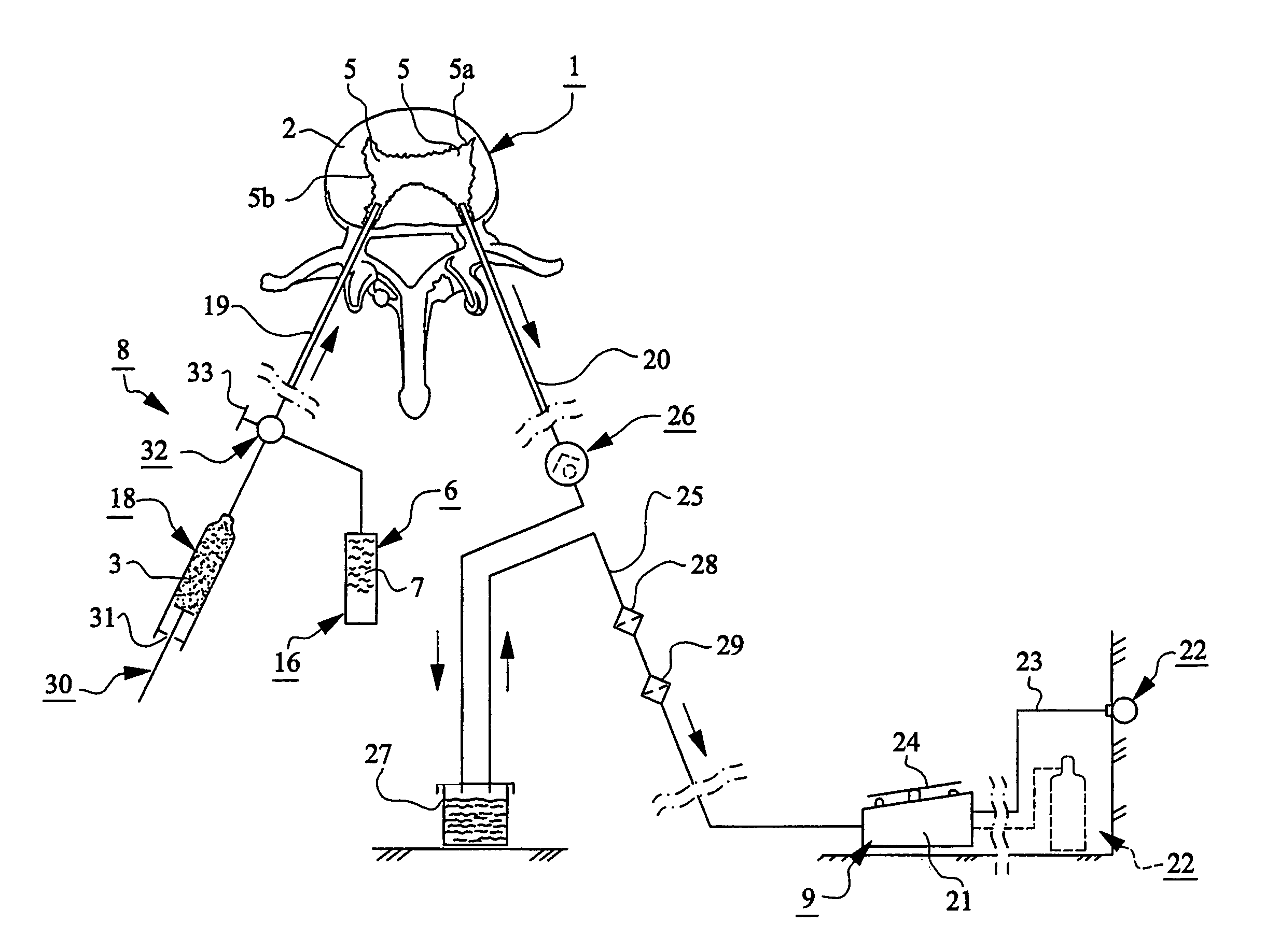
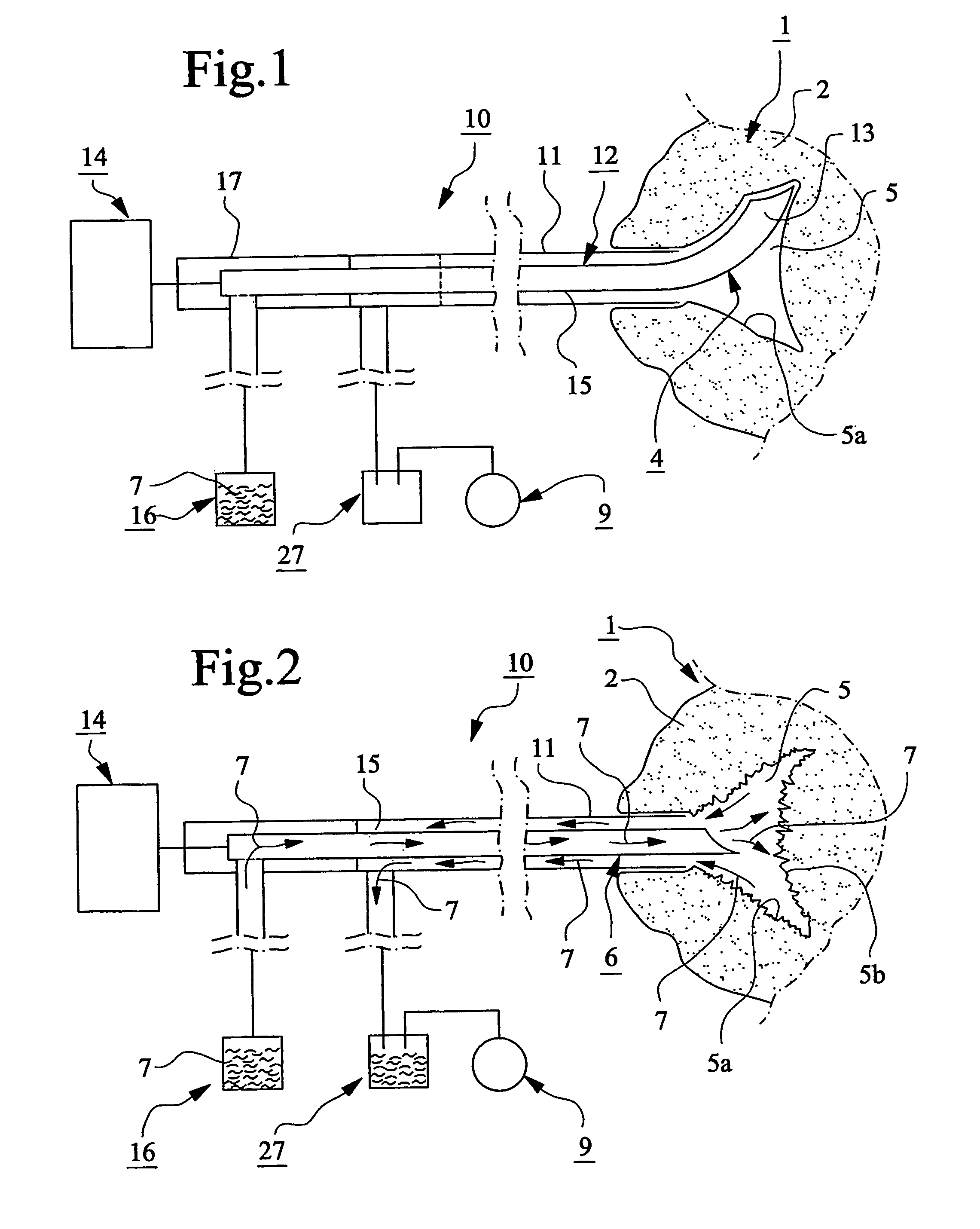
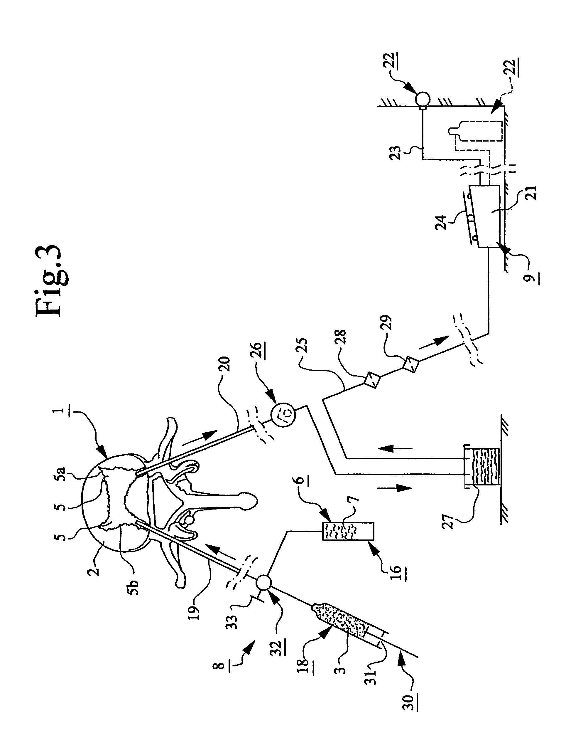
[0014]In the figures, different parts of a device for preparing spongy bone 1, e.g. a vertebra 2, to receive bone substitute and / or bone reinforcing material 3, and for locating said material in said vertebra is schematically illustrated. Said device comprises at least one perforating device 4 for making at least one hole 5 in the vertebra 2, at least one flushing or rinsing device 6 for flushing or rinsing said hole with rinsing agent 7 and at least one supply device 8 which permits suction and / or insertion of bone substitute and / or bone reinforcing material 3 into the vertebra.

[0015]At least one vacuum source 9 is provided to generate a vacuum in the hole 5 in the vertebra 2 for sucking and / or facilitate insertion of bone substitute and / or bone reinforcing material 3 into said vertebra.

[0016]The perforating device 4 can be designed in many different ways and so can also the rinsing device 6. At the exemplary embodiment of FIGS. 1 and 2, the perforating and rinsing devices 4, 6 are...


PUM


Abstract

The present invention relates to a device for providing spongy bone with bone substitute and / or bone reinforcing material, wherein at least one perforating device (4) is provided for making at least one hole (5) in the spongy bone (1) and wherein at least one flushing or rinsing device (6) is provided for flushing or rinsing the hole (5) with a rinsing agent (7). At least one vacuum source (9) is provided for generating a vacuum in the hole (5) in the spongy bone (1) for sucking and / or facilitating insertion or feeding of the bone substitute and / or bone reinforcing material (3) into said spongy bone (1). The invention also relates to bone substitute and / or bone reinforcing material and methods in connection with the invention.

Description

FIELD OF THE INVENTION[0001]The present invention relates to a device for providing spongy bone with bone substitute and / or bone reinforcing material, wherein at least one perforating device is provided for making at least one hole in the spongy bone and wherein at least one flushing or rinsing device is provided for flushing or rinsing the hole with a rinsing agent. The invention further relates to a bone substitute and / or bone reinforcing material and a method.BACKGROUND OF THE INVENTION[0002]Vertebroplasty is a technique according to which biocompatible material is injected into a spongy vertebra. After some time, the injected material hardens, whereby an inner support is obtained for fixing the vertebra and thereby alleviate pain and reduce the risk of vertebral collapse.[0003]The material is injected into the vertebra through a needle and in doing so, it is necessary to subject the material to high pressure, often one or more MPa. Hereby, there is an obvious risk that tissue ma...

Claims


Application Information

Patent Timeline
Patent Type & Authority Patents(United States)
IPC IPC(8): A61M37/00A61B17/16A61B17/88A61F2/00A61F2/46
CPCA61B17/1615A61B17/1637A61B17/8822A61B17/8827A61F2310/00293A61F2/4601A61F2/4675A61F2002/4685A61B17/88A61B17/16A61F2/00A61F2/46
Inventor LIDGREN, LARSLUNDGREN, TORGNYARVIDSSON, PARJONSSON, SVEN
Owner TEG HLDG
Learn More