
Harvesting energy from vehicular vibrations using piezoelectric devices

a piezoelectric device and vehicular vibration technology, applied in the field of system for generating power, can solve the problems of large effort, vehicle vibration, and undesirable vibrations, and achieve the effect of reducing the number of vibrations, and reducing the frequency of vibrations

Inactive Publication Date: 2011-05-03
GM GLOBAL TECH OPERATIONS LLC
View PDF39 Cites 34 Cited by
  • Summary
  • Abstract
  • Description
  • Claims
  • Application Information

AI Technical Summary

Benefits of technology

The system effectively converts vehicular vibrations into electrical energy, enhancing fuel economy by utilizing otherwise lost energy without compromising suspension performance.

Problems solved by technology

It is generally known that vehicles are subjected to vibrations, especially while being driven.
These vibrations have typically been considered undesirable.
In fact, a great deal of effort has gone into the development of suspension systems that include springs, dampers, shock absorbers, and the like, that provide vehicular stability and insulate the vehicle's passenger compartment from vibration caused by, for example, driving on bumpy or otherwise tortuous roadways.
Currently, the energy associated with these vibrations is lost.

Method used


Image

  • Harvesting energy from vehicular vibrations using piezoelectric devices
  • Harvesting energy from vehicular vibrations using piezoelectric devices
  • Harvesting energy from vehicular vibrations using piezoelectric devices

Examples


Embodiment Construction

[0014]The following detailed description is merely illustrative in nature and is not intended to limit the invention or the application and uses of the invention. Furthermore, there is no intention to be bound by any expressed or implied theory presented in the preceding technical field, background, brief summary or the following detailed description. The invention may be described herein in terms of functional and / or logical block components and various processing steps. It should be appreciated that such block components may be realized by any number of hardware, software, and / or firmware components configured to perform the specified functions. For the purposes of conciseness, conventional techniques and systems related to semiconductor processing, transistor theory, packaging, and power modules are not described in detail herein.

[0015]The following description refers to elements or nodes or features being “connected” or “coupled” together. As used herein, unless expressly stated...


PUM


Abstract

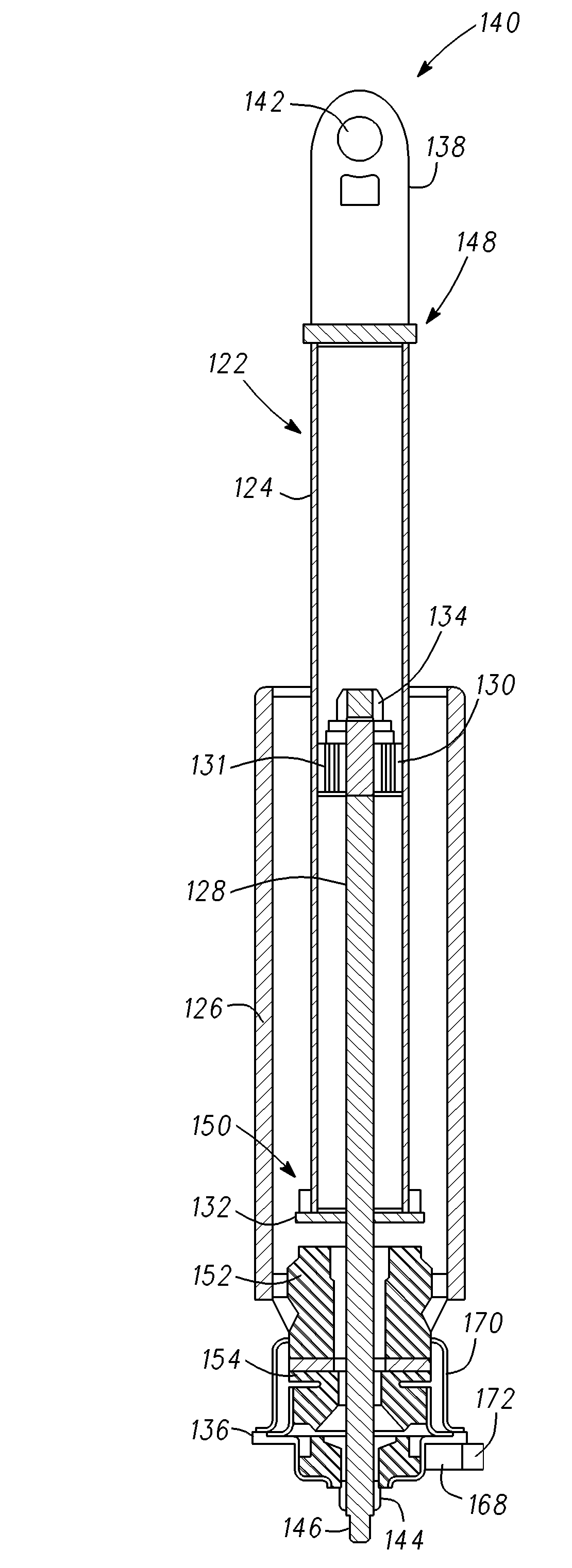
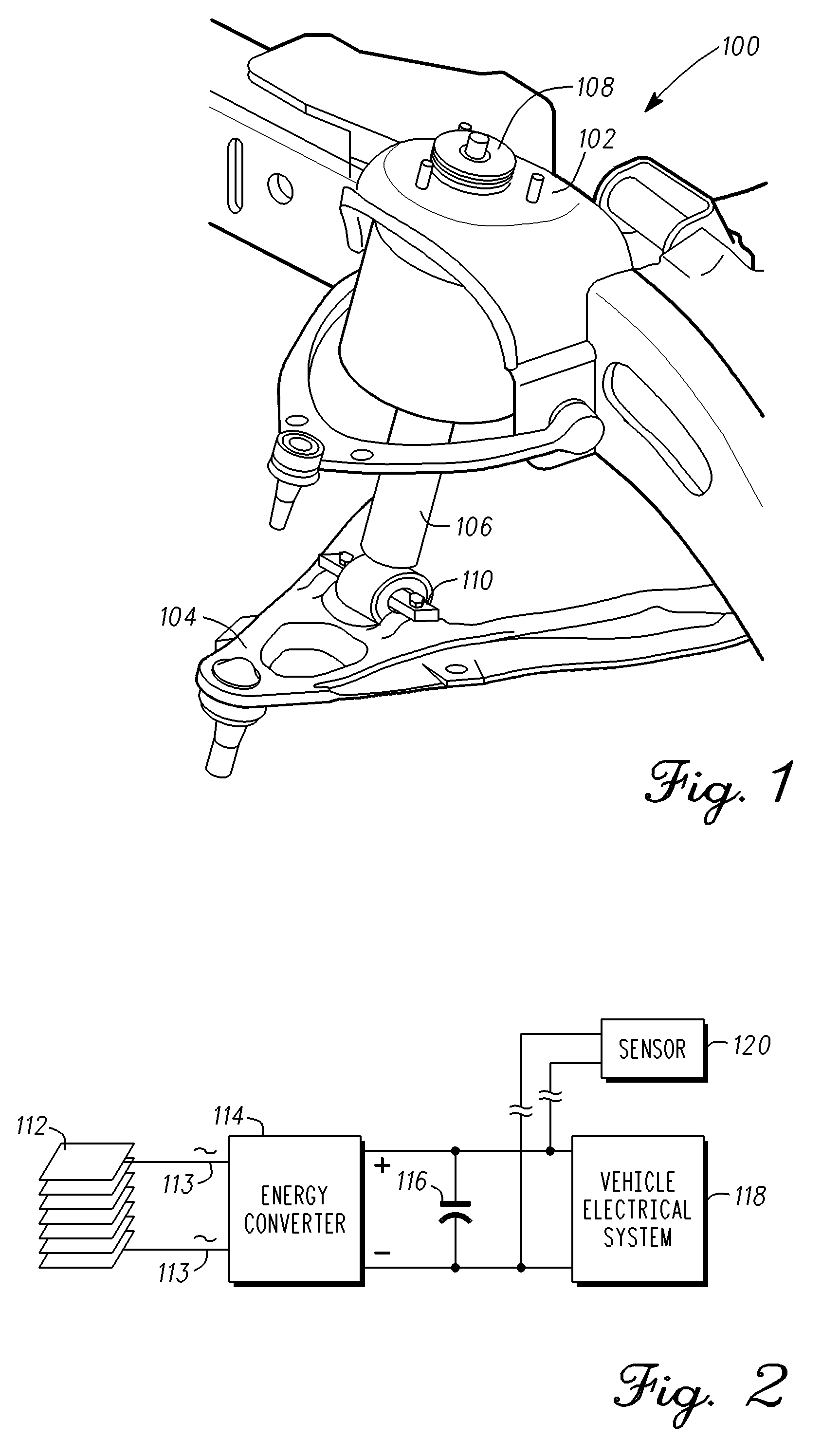
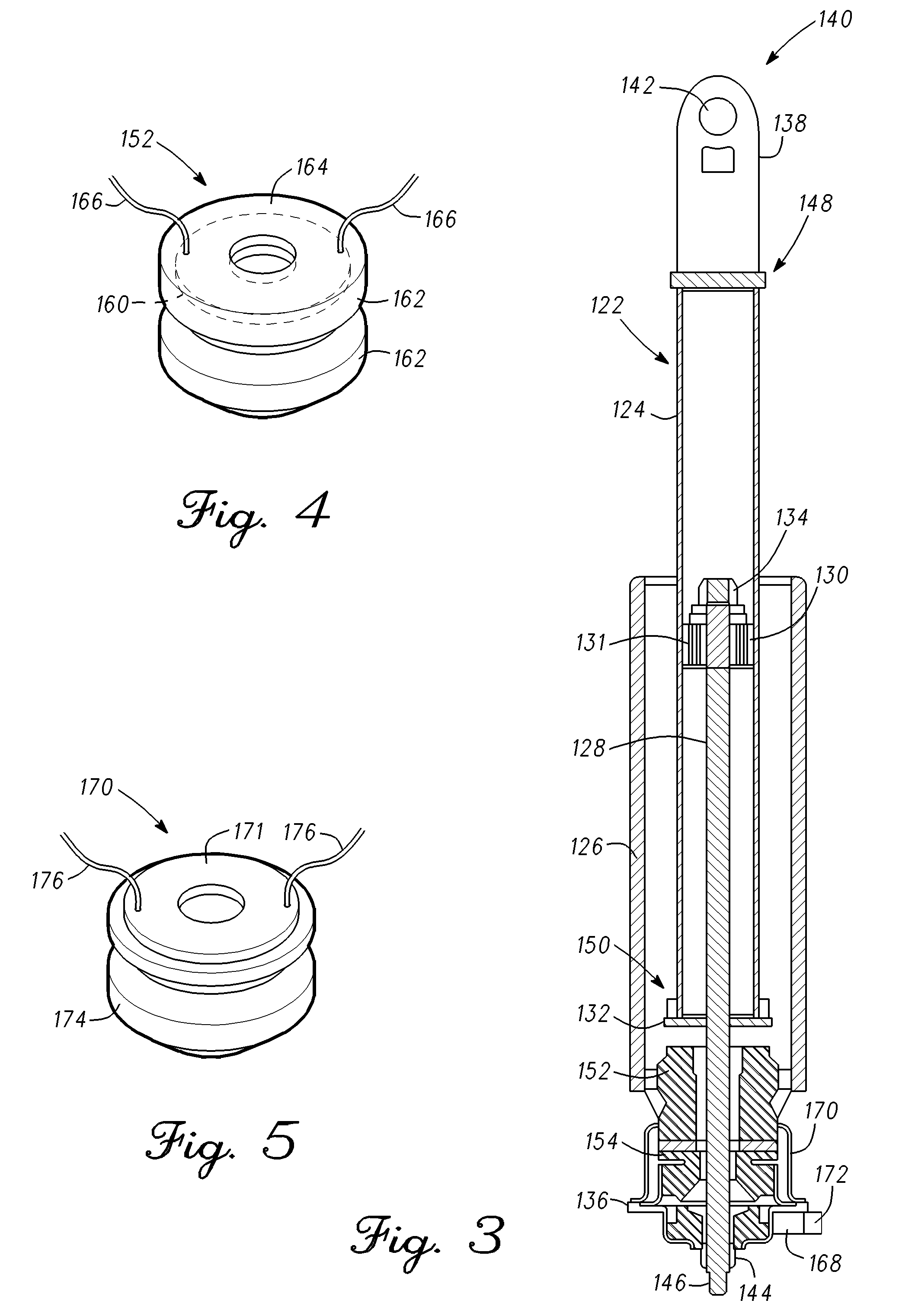
An energy harvesting apparatus, for deployment on a vehicle, comprises a shock absorber, including a dust tube assembly, a jounce bumper assembly mounted within the dust tube assembly at a first end thereof, and a damper tube mounted for telescopic movement through a second end of the dust tube, the jounce bumper assembly configured for impact with the damper tube. A piezoelectric device is coupled to the jounce bumper assembly.

Description

TECHNICAL FIELD[0001]This relates generally to a system for generating power and, more particularly, to a system for harvesting energy from vehicular vibrations utilizing piezoelectric devices.BACKGROUND OF THE INVENTION[0002]Increasing demands for better fuel economy have lead to improvements and developments in hybrid vehicles, electric vehicles, and vehicles powered by fuel cells or diesel fuel. Efforts on the part of the automotive industry to increase fuel economy have included, but are not limited to, reductions in mass, improved aerodynamics, active fuel management, direct injection engines, homogeneous charge compression ignition engines, and hybrid engines. Still, other mechanisms, techniques, and energy sources that will improve fuel economy are continually being sought. To this end, the use of piezoelectric materials to harvest energy has received a great deal of attention in recent years. As is well known, the piezoelectric effect involves the conversion of mechanical st...

Claims


Application Information

Patent Timeline
Patent Type & Authority Patents(United States)
IPC IPC(8): H01L41/113H10N30/30
CPCB60G13/14H02N2/186F03G7/08B60G2200/144B60G2300/60H02N2/183
Inventor NAMUDURI, CHANDRA S.LI, YUNJUNTALTY, TIMOTHY J.ELLIOTT, ROBERT B.MCMAHON, NANCY
Owner GM GLOBAL TECH OPERATIONS LLC
Learn More