
Rheometer allowing direct visualization of continuous simple shear in non-newtonian fluid

a simple shear and rheometer technology, applied in the field of rheometers, can solve the problems of lack of clarity and depth of field in the visual representation of material undergoing change, lack of adequate complete description, and state of the art not including simultaneous rheological measurements

Inactive Publication Date: 2011-05-17
THE UNIVERSITY OF AKRON
View PDF0 Cites 3 Cited by
  • Summary
  • Abstract
  • Description
  • Claims
  • Application Information

AI Technical Summary

Benefits of technology

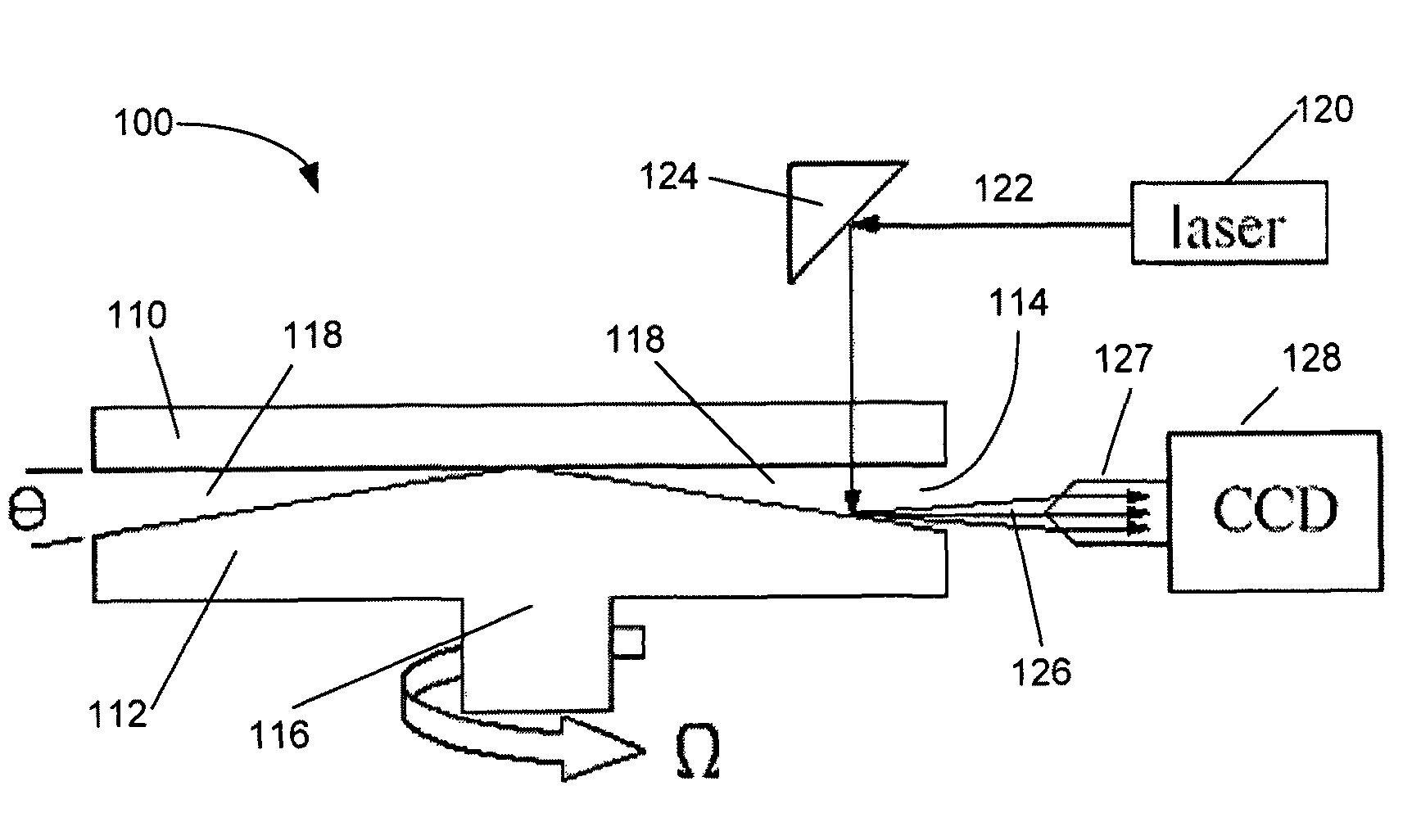
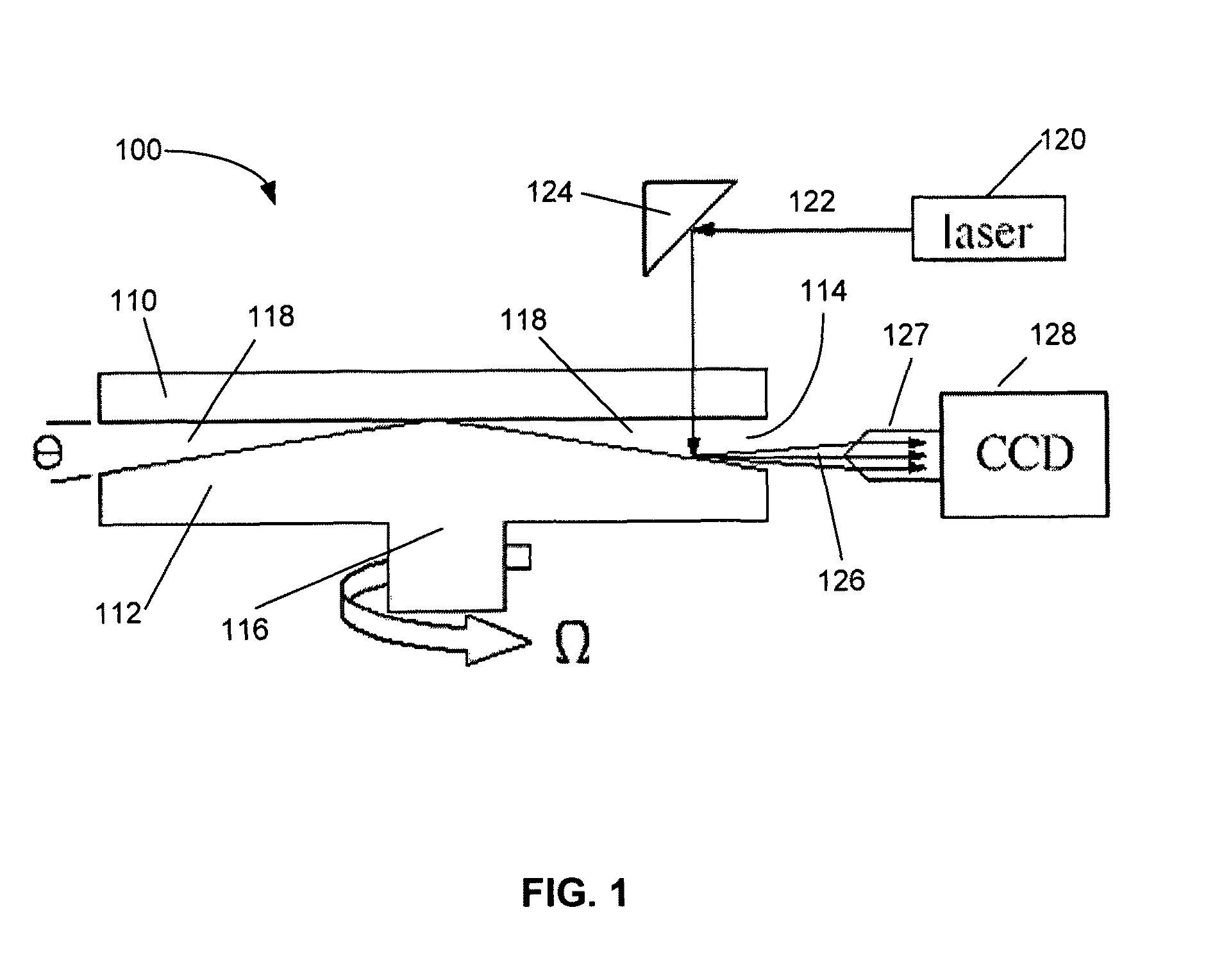
The present invention is a rheometric device that allows for direct visualization of the material being tested. It can determine the velocity and strain field across the material, as well as the morphology of the flow. The device can be used with current shearing rheometers and has multiple angles of visualization. It includes an optically transparent fixed surface and a moving surface in a perpendicular relation to the fixed surface, with an optically transparent barrier between them. The moving surface can create a torque on the material being tested. The device also includes at least one laser and visual receiving means to monitor the material. The invention provides versatility and allows for monitoring the flow characteristics of materials.

Problems solved by technology

At present visual representations of the material undergoing change lack clarity and depth of field.
Structured fluids such as foams, colloids, micelles, granular materials and polymers display intricate dynamic behavior that lack an adequately complete description.
However, the state of the art does not include simultaneous rheological measurements in conjunction with direct visualization and determination of the velocity field within the sample fluid.
Thus, the art lacks devices and methods for direct visualization of velocity fields within rheological samples and lacks methods for visualizing the morphology of sheared samples along the velocity gradient direction.

Method used


Image

  • Rheometer allowing direct visualization of continuous simple shear in non-newtonian fluid
  • Rheometer allowing direct visualization of continuous simple shear in non-newtonian fluid
  • Rheometer allowing direct visualization of continuous simple shear in non-newtonian fluid

Examples


Embodiment Construction

[0029]The present invention relates to a rheometric device which provides a direct visualization of the subject material. The device also determines the velocity and / or the strain field across the thickness and the morphology to be determined across the same gap. The invention relates both to a device and / or method that can be used in connection with current shearing rheometers, and similar apparatus. The present invention also relates to a process for making a shear rate measurement. The invention provides versatility by allowing multiple angles of visualization which properly characterizes the flow characteristics and shear rates involved.

[0030]As used herein, the terms “one embodiment”, “another embodiment”, “some embodiments”, and similar phrases, refers to one or more embodiments. Furthermore, the phrases may or may not refer to the same embodiment. Additionally as used herein, approximating language may be applied to modify any quantitative representation that could permissibl...


PUM

PropertyMeasurementUnit
diameteraaaaaaaaaa
diameteraaaaaaaaaa
oblique angleaaaaaaaaaa

Abstract

The present invention relates to a rheometric device which provides a direct visualization of the subject material. The device also determines the velocity and / or the strain field across the thickness and the morphology to be determined across the same gap. The invention relates both to a device and / or method that can be used in connection with current shearing rheometers, and similar apparatus. The present invention also relates to a process for making a shear rate measurement. The invention provides versatility by allowing multiple angles of visualization which properly characterizes the flow characteristics and shear rates involved.

Description

RELATED APPLICATION DATA[0001]This application is a continuation-in-part of co-pending International Application Number PCT / US2006 / 033969, with an international filing date of Aug. 31, 2006, entitled “Rheometer Allowing Direct Visualization of Continuous Simple Shear in Non-Newtonian Fluids,” which published as WO2007 / 027850 on Mar. 8, 2007, which in turn claims priority to previously filed U.S. Provisional Application No. 60 / 712,936, filed on Aug. 31, 2005, entitled “Rheometer Allowing Direct Visualization of Continuous Simple Shear in Non-Newtonian Fluids”, both of which are hereby incorporated by reference in their entireties.[0002]This invention was made with government support under grants, ACS-PRF grant (40596-AC7) and NSF grant (CTS-0115867). The United States government may have certain rights to the invention or inventions herein.FIELD OF THE INVENTION[0003]The present invention relates to a rheometric device which provides a direct visualization of the subject material. Th...

Claims


Application Information

Patent Timeline
Patent Type & Authority Patents(United States)
IPC IPC(8): G01N11/14
CPCG01N11/14G01P5/26G01N2011/008
Inventor WANG, SHI-QING
Owner THE UNIVERSITY OF AKRON
Learn More