Overlapped stents for scaffolding, flexibility and MRI compatibility

a scaffolding and stent technology, applied in the field of scaffolding stents with overlaps, flexibility and mri compatibility, can solve the problems of poor scaffolding, poor side branch access and expandability, distortion of mri images,

Inactive Publication Date: 2011-05-17
BOSTON SCI SCIMED INC
View PDF54 Cites 15 Cited by
  • Summary
  • Abstract
  • Description
  • Claims
  • Application Information

AI Technical Summary

Problems solved by technology

Eddy currents, however, are know to cause distortions in MRI images.
A stent with a larger, more open geometry will have an improved side branch access and expandability but poorer scaffolding.
Smaller, tight geometry results in better scaffolding, but poor side branch access and expandability.

Method used


Image

  • Overlapped stents for scaffolding, flexibility and MRI compatibility
  • Overlapped stents for scaffolding, flexibility and MRI compatibility
  • Overlapped stents for scaffolding, flexibility and MRI compatibility

Examples


Embodiment Construction

[0051]While this invention may be embodied in many different forms, there are described in detail herein several specific embodiments of the invention. This description is an exemplification of the principles of the invention and is not intended to limit the invention to the particular embodiments illustrated.

[0052]For the purposes of this disclosure, like reference numerals in the figures shall refer to like features unless otherwise indicated.

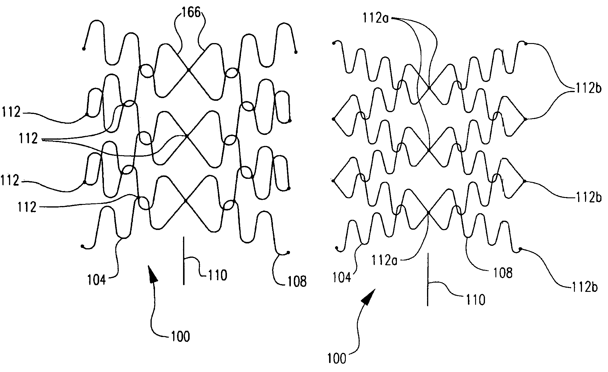
[0053]In one embodiment, the invention is directed to a tubular insert for a bodily vessel. The insert, as shown generally in the flat at 100 in FIG. 2c, comprises an inner stent 104 and an outer stent 108. At least a portion of inner stent 104 is disposed within the outer stent 108. The outer stent has a longitudinal axis 110 and is constructed so as to be free of any closed loops which are electrically conductive and which are disposed about the longitudinal axis such that the longitudinal axis passes through the closed loop. The inner sten...


PUM


Abstract

A tubular insert for a vessel comprises an inner stent and an outer stent. At least a portion of the inner stent is disposed within the outer stent. The outer stent has a longitudinal axis and is constructed to be free of any closed loops which are electrically conductive and which are disposed about the longitudinal axis such that the longitudinal axis passes through the closed loop. The inner stent has a longitudinal axis and is constructed so as to be free of any closed loops which are electrically conductive and which are disposed about the longitudinal axis such that the longitudinal axis passes through the closed loop. There is a substantially electrically non-conductive connection between the inner and outer stents. Desirably, a wall surface is defined by the outer and inner stents, and there are no closed, electrically conductive loops in the wall surface of the tubular insert.

Description

CROSS-REFERENCE TO RELATED APPLICATIONS[0001]This application is a Continuation application from Application No. 10 / 864,665, filed Jun. 9, 2004, the contents of which is hereby incorporated by referenceBACKGROUND OF THE INVENTION[0002]A stent is a generally tubular device that is used to support a bodily lumen. A stent is typically delivered to a desired bodily location via a catheter.[0003]Magnetic resonance imaging (MRI) has been widely used to image various parts of the body. One of the uses of MRI has been to image blood flow. It is, therefore, desirable for stents to be MRI compatible to allow for imaging of vessels in the region of a stent. Although there has been a great deal of activity focusing on the choice of materials for MRI compatible stents, other factors in the design of the stent must be considered as well.[0004]For example, a stent that is made from an electrically conductive material that is formed in electrically conductive loops which extend fully around the lon...

Claims


Application Information

Patent Timeline
Patent Type & Authority Patents(United States)
IPC IPC(8): A61F2/86A61B19/00A61F2/00A61F2/852A61F2/88A61F2/89A61F2/90A61F2/91A61F2/915G01R33/28
CPCA61F2/90A61F2/91A61F2/915G01R33/285A61F2/88A61F2/852A61F2230/0013A61F2/885A61F2002/91508A61F2002/91516A61F2002/91533A61F2002/9155A61F2002/91558A61F2002/91591A61F2250/0045A61F2250/0062A61F2250/0063A61F2250/0067A61F2/89A61F2210/0076A61F2230/0054
Inventor GREGORICH, DANIEL
Owner BOSTON SCI SCIMED INC
Why Eureka
Try Eureka