
Sealed contactor

a contactor and sealing technology, applied in the field of sealing contactors, can solve the problems of affecting the service life of the contactor, the failure rate of the contactor, so as to achieve the effect of easy and flexible manufacturing, less cost, and long li

Active Publication Date: 2011-05-17
GIGAVAC INC
View PDF7 Cites 69 Cited by
  • Summary
  • Abstract
  • Description
  • Claims
  • Application Information

AI Technical Summary

Benefits of technology

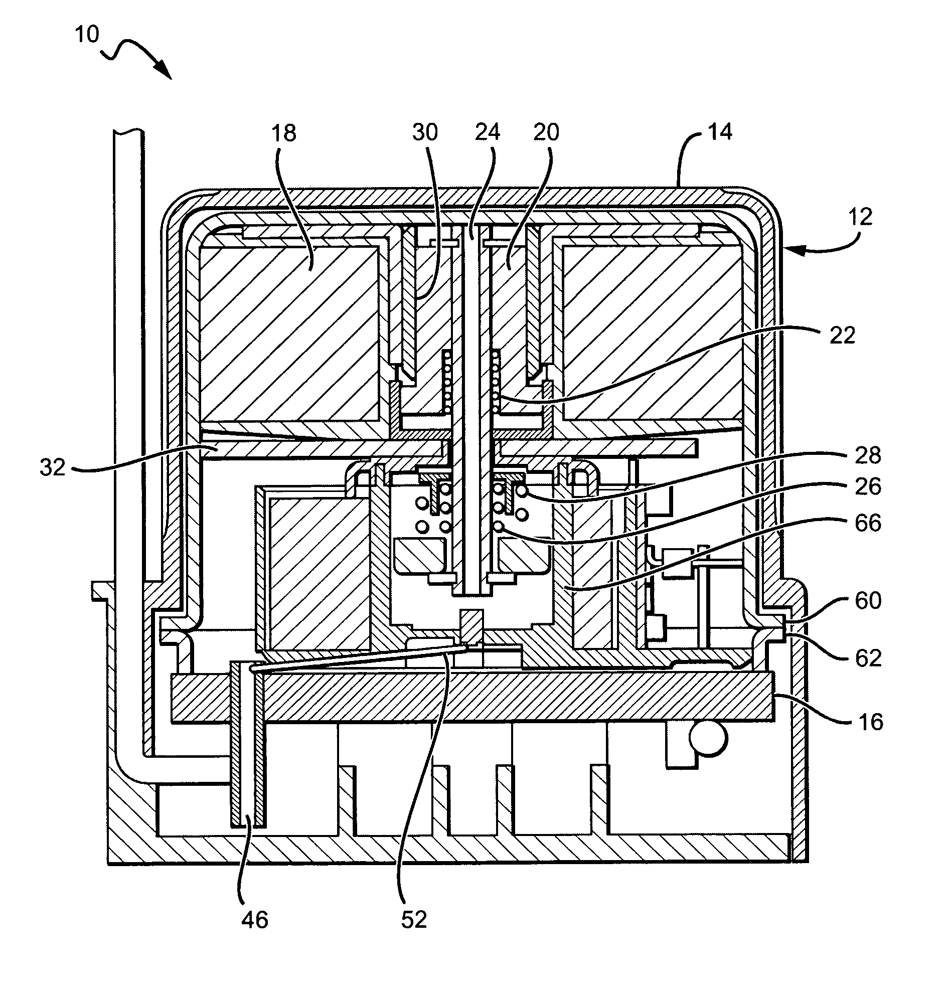
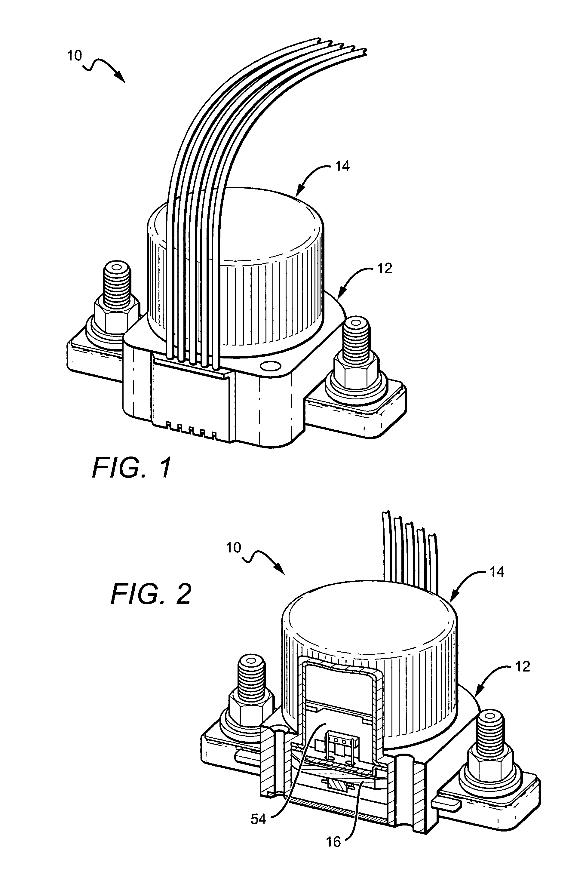
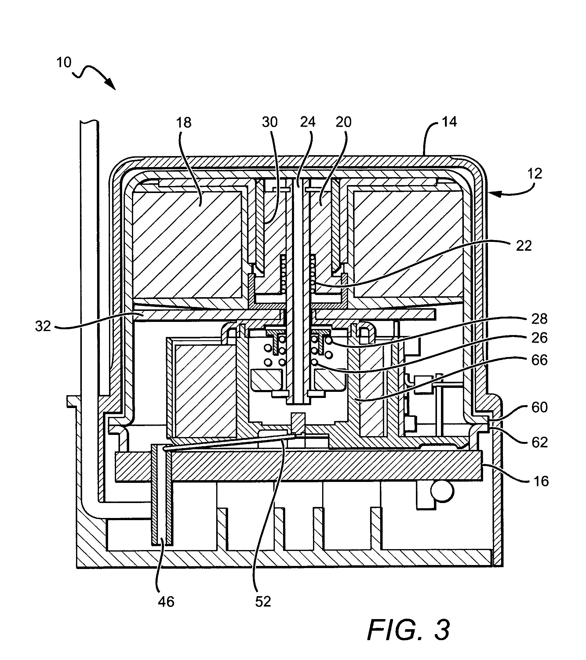
[0015]The present invention provides sealed contactors that are less expensive, easier and more flexible to manufacture, yet still exhibit long life and reliable high voltage operation. One embodiment of a solenoid driven contactor according to the present invention comprises a hermetically sealed housing having internal components for changing the state of said contactor, with the housing comprising a cup for holding the internal components and a header covering said cup with an airtight seal. Terminals are included that are electrically connected to the internal components for connection to circuitry and for applying an electrical signal to control the state of the contactor. Power-reducing electronics are also included and are located inside the hermetically sealed housing.

Problems solved by technology

Ceramic housings, however, can be expensive and difficult to manufacture.
Traditional ceramic headers can be difficult and expensive to manufacture because they are complex shapes that require special tooling, difficult metallization, and time consuming post processes.
Epoxy sealed housings can be more prone to failure at high temperature and the all-ceramic envelope products can be very expensive.
While the use of flat ceramic can be used, one problem is that the arc chamber is separate from the header.
To properly seal the chamber, epoxy or a brazement could be used, however they must be exact solutions dimensionally and can reduce the performance and / or increase the price.
Sealed solenoid driven contactors can be problematic due to pressure build-up on one side of the plunger during plunger travel.
This imbalance of pressure slows plunger movement and can reduce solenoid performance.
Having strong springs requires a large amount of coil power to operate the contactor.
However, traditional two coil designs can be costly and / or can be problematic due to power-reducing components often comprise mechanical switches that are located outside of the contactor.
This can expose the components to the hazards of the external environment, which can reduce the efficiency and life of the contactor.
However, the spring force can be greater than the solenoid force, which can cause the solenoid actuator to stall as it is moving and fail to close.

Method used


Image

  • Sealed contactor
  • Sealed contactor
  • Sealed contactor

Examples


Embodiment Construction

[0030]The present invention provides a low cost, high-powered, solenoid-driven contactor in a hermetically sealed housing. The housing includes a flat, low cost ceramic header that provides an airtight seal. This allows the header to be manufactured using low cost materials and processes, while still providing a housing that can be gas filled under pressure to provide reliable high voltage operation through a long life cycle. The flat ceramic header also provides for inexpensive tooling, simple metallization and uncomplicated post processes while providing electrical isolation between the contacts.

[0031]Inside the housing, a plunger with a hollow shaft is included. Sealed solenoid-driven contactors are known to have pressure build up on one side of the plunger during travel, which can slow plunger movement and reduce performance. The hollow shaft enables improved plunger movement since gas in the sealed housing can flow freely and pressure can equalize during plunger travel.

[0032]Al...


PUM


Abstract

A low cost, sealed contactor comprises a hermetically sealed housing with a flat header having internal components for changing the state of said contactor. Terminals are electrically connected to the internal components for connection to internal circuitry and applying an electrical signal to control the state of the contactor. A solenoid-driven plunger with a hollow shaft is included. Power-reducing electronics located within the hermetically sealed housing are also included. Two contact springs are also included to improve electrical performance. O-rings are added to help seal the contactor and keep it hermetically sealed.

Description

[0001]This application claims the benefit of provisional application Ser. No. 60 / 844,063 to Mike Molyneux et al, which was filed on Sep. 11, 2006.BACKGROUND OF THE INVENTION[0002]1. Field of the Invention[0003]The present invention relates to sealed contactors, and particularly to low cost sealed contactors in hermetically sealed housings.[0004]2. Description of the Related Art[0005]Hermetically sealed contactors are magnetically-operated devices used for repeatedly establishing and interrupting an electrical power circuit and for switching of high electrical currents and / or high voltages. They typically have fixed and movable internal contacts, and an internal actuating mechanism supported within a hermetically sealed housing. In one type of contactor, air is removed from the contactor housing to create a vacuum that suppresses arc formation, provides long operating life and allows for low resistance operation of the contactor. In another type of contactor, the evacuated chamber ca...

Claims


Application Information

Patent Timeline
Patent Type & Authority Patents(United States)
IPC IPC(8): H01H13/04
CPCH01H50/023H01H51/29H01H2050/025
Inventor SWARTZENTRUBER, BRENT J.MOLYNEUX, MIKESULLIVAN, DANIEL C.
Owner GIGAVAC INC
Learn More