High-availability communication system

a communication system and high-availability technology, applied in the field of communication systems, can solve the problems of high cost, inconvenient switching back and forth, and inconvenient switching back and forth, and achieve the effect of rapid switching back

Active Publication Date: 2011-05-17
SIEMENS AG
View PDF3 Cites 10 Cited by
  • Summary
  • Abstract
  • Description
  • Claims
  • Application Information

AI Technical Summary

Benefits of technology

[0015]A further advantageous development of the invention is characterized in that all communication stations are equipped for sending and receiving payload data telegrams. As a result of this, faults that are detected can be notified within the framework of the network by all communication stations and e.g. a switchover of the communication channels using the described method can be done by all communication stations. This has the advantage that, irrespective of where the fault occurs, it can be detected immediately and the switchover to the redundant communication channel can be initiated.
[0030]For the purpose of implementing the solution, use is made of the fact that in terms of availability it is sufficient for one channel to be declared as primary channel and for the other channel or channels to work as backup. In this context, it is never necessary in practice to switch rapidly back and forth between the channels, since a defective field bus component remains defective until it is repaired. Therefore no switching back to this channel takes place during this time. The typical repair time is approximately four hours in this type of arrangement. Components which only function sporadically are generally not suitable for high-availability equipment, and therefore rapid switching back and forth is not necessary here either. The present solution also has the advantage that non-cyclical services such as a peripheral alarm or a non-cyclical payload data telegram are assigned a specific transport path, this being the primary channel in each case.

Problems solved by technology

However, it is disadvantageous in this context that the switchover telegrams which are transferred when the fault is detected are transmitted asynchronously relative to the cyclical payload data, and additional measures are therefore required, e.g. the introduction of a wait time or a delay time, in order to prevent a so-called switchover impact.
In particular, such a solution is not suitable for redundant connections having significantly differing propagation times, where the redundantly arranged components are widely dispersed in the framework of the network topology or are situated at different locations of the network such that the data telegrams require significantly differing propagation times in order to be sent from a corresponding sender to the redundant components, since the switchover telegram possibly reaches the redundant partners at a time which differs significantly between the redundant partners.
In this type of arrangement, the disadvantage is again that switchover telegrams are required for switching over between the preferred channel and the reserve channel, wherein said switchover telegrams are transmitted asynchronously relative to the cyclical payload data.
This method has the disadvantage of being very costly and requires a close coupling between the two redundantly arranged recipients since the telegram numbers must be compared continuously in order to decide which is the most recent data telegram and hence which data telegram is to be used.
However, such a method is unsuitable e.g. in the case of systems which are widely distributed in physical terms, where the redundant components, e.g. the control units in an automation system, are widely separated and therefore the distance between the redundant field bus controllers can be greater than 1000 m. Moreover, in such a case the field bus controllers would not be able to feature a dedicated individual communication connection via which the number comparison can take place.

Method used


Image

  • High-availability communication system
  • High-availability communication system
  • High-availability communication system

Examples


Embodiment Construction

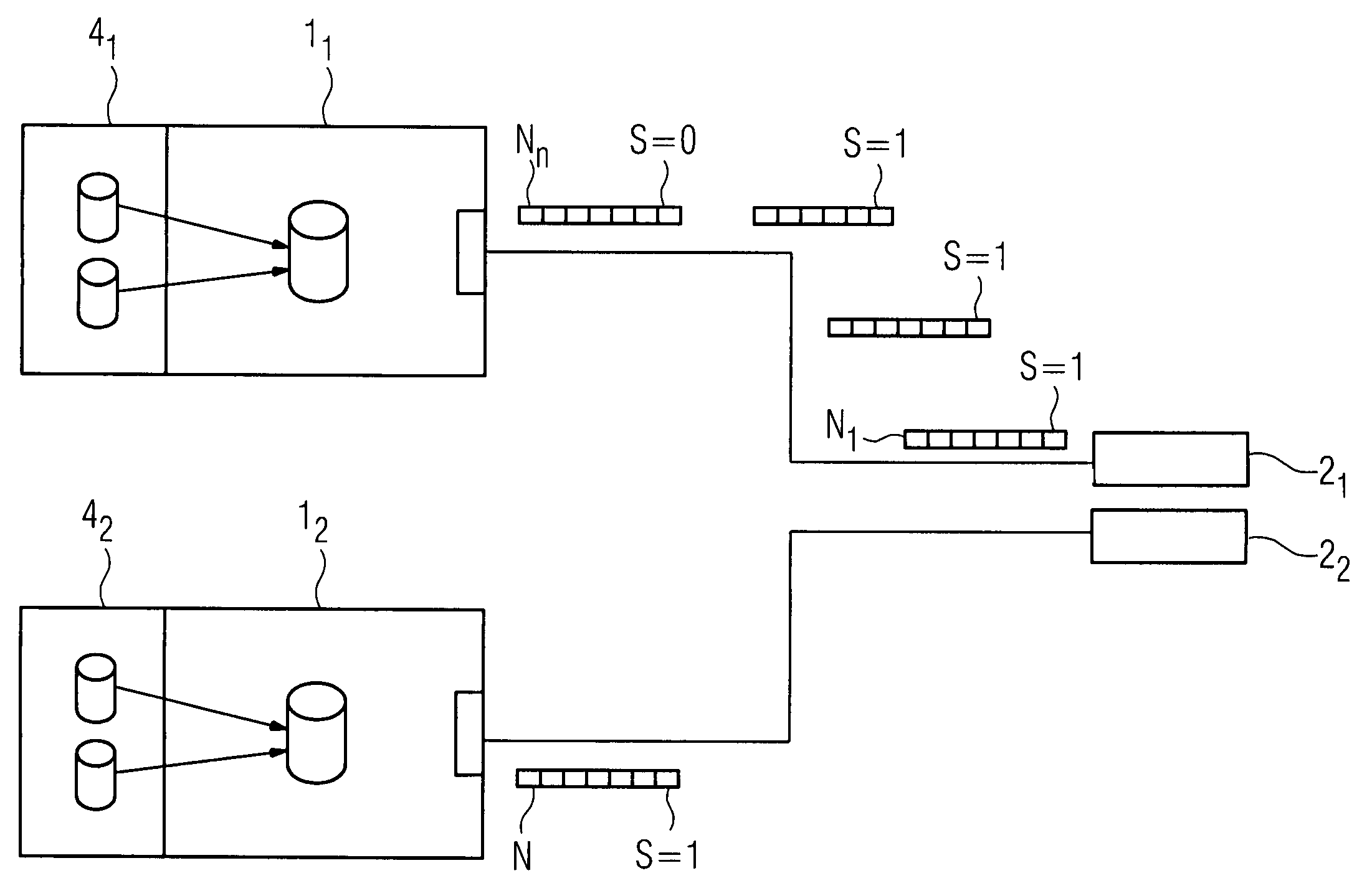
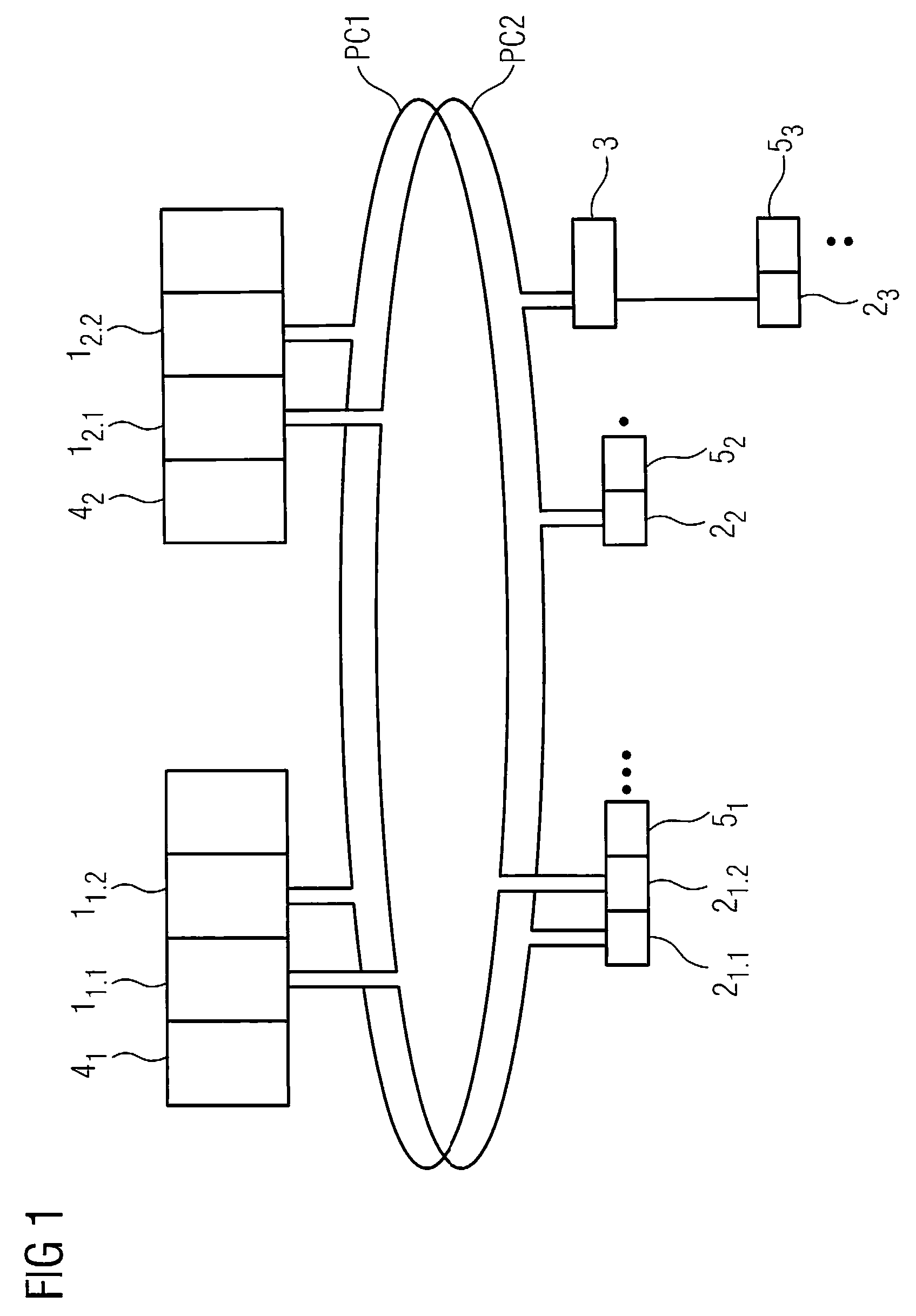
[0040]The network architecture of a redundant system, in particular in the field of automation, is illustrated by way of example in FIG. 1. In the system, the communication stations 1,2 are connected together via redundantly arranged communication connections PC1, PC2. The communication connections are configured in the form of a ring here. The communication stations 1,2 can be e.g. senders such as field bus controllers 1, which in each case transmit the data of a so-called host, e.g. a CPU 4, via the communication system to data recipients, e.g. interface modules 2, which in turn are connected to field devices 5. In this context, the individual senders and recipients can be arranged redundantly or singly in each case. So-called switches 3 for a desired distribution of the data that is sent via the communication system can also be present within the framework of the architecture.

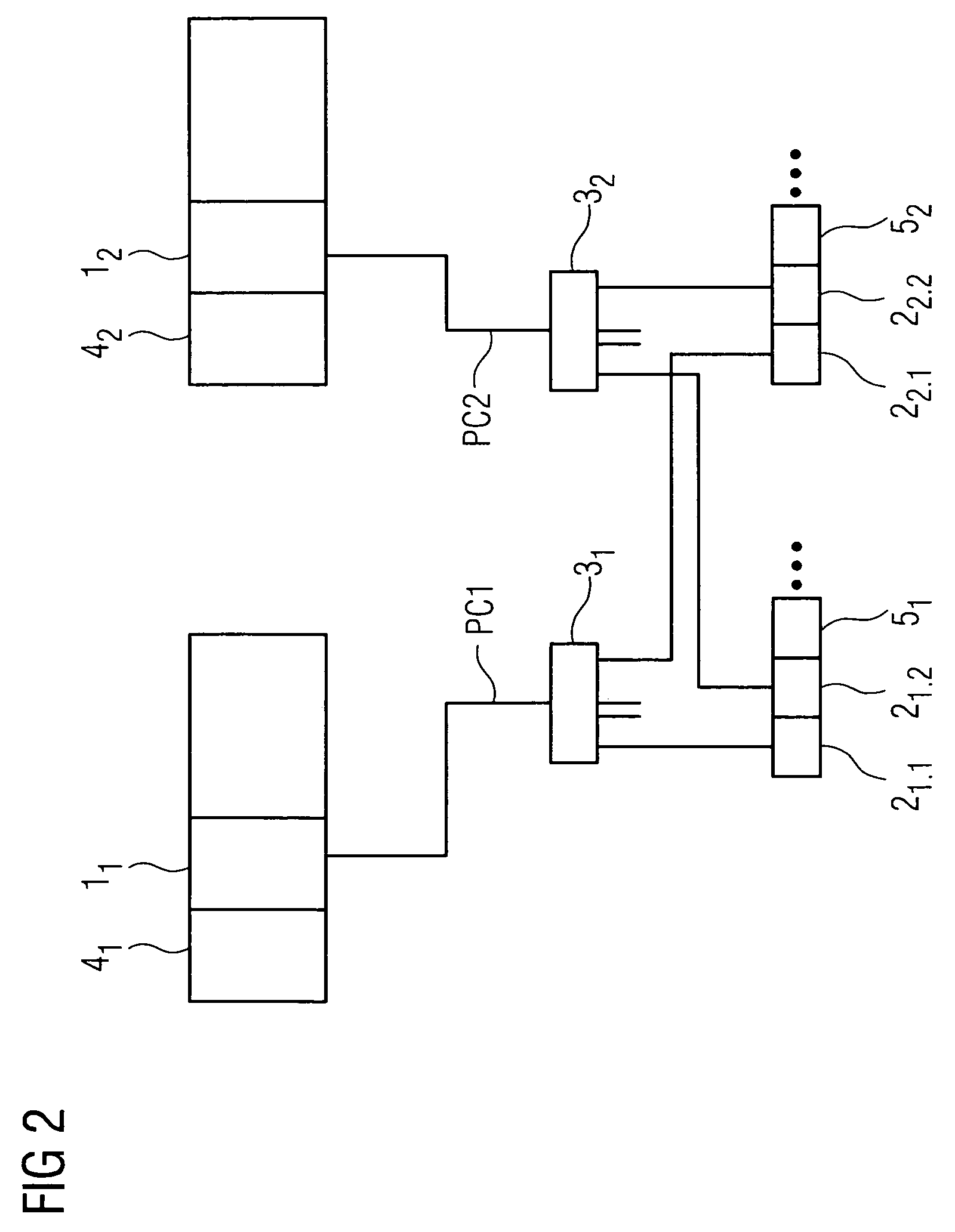
[0041]FIG. 2 shows a further possible architecture of a corresponding communication system with communica...


PUM


Abstract

There is described a communication system for reliable communication between communication stations, wherein there is at least one communication connection between the communication stations, wherein the communication connection features at least two channels for transmitting payload data telegrams, wherein only one channel acts as primary channel for the communication at any time, and wherein the other channels are provided as backup channels. A status indicator in the payload data telegram is provided for the indication of information concerning which channel is primary channel or backup channel at a given time point, wherein the communication stations adopt as primary channel that channel for which, during receipt of the payload data telegrams, the most recent status change from backup channel to primary channel was detected by the communication stations.

Description

CROSS REFERENCE TO RELATED APPLICATIONS[0001]This application claims priority of European Patent Office application No. 07017367.9 EP filed Sep. 5, 2007, which is incorporated by reference herein in its entirety.FIELD OF INVENTION[0002]The invention relates to a communication system for reliable communication between communication stations and to a method for reliable communication between communication stations.BACKGROUND OF INVENTION[0003]In systems in which the individual communication stations perform important functions and in which the communication taking place between the communication stations must be carried out in an uninterrupted manner, use is normally made of redundantly arranged communication channels such that even if one channel fails a data transmission can take place on the corresponding other channel between communication stations. The communication stations themselves can be e.g. field devices or control units in an automation system. In this context, the commun...

Claims


Application Information

Patent Timeline
Patent Type & Authority Patents(United States)
IPC IPC(8): H04L12/28H04L69/40
CPCG05B19/0428H04L12/40H04L69/14H04L69/40H04L12/437G05B2219/24175H04L2012/4026
Inventor BARTHEL, HERBERTGRIESSBAUM, REINERRAMM, ENRICOSTEINDL, GUNTER
Owner SIEMENS AG
Why Eureka
Try Eureka