Dual level bicycle parking system

a bicycle and parking system technology, applied in the field of parking systems, can solve the problems of preventing some users, affecting the use of bicycles in the surrounding area, and affecting the use of bicycles by users less physically capable, and achieve the effect of facilitating the loading and unloading of bicycles

Inactive Publication Date: 2011-05-24
SARIS EQUIP LLC
View PDF125 Cites 41 Cited by
  • Summary
  • Abstract
  • Description
  • Claims
  • Application Information

AI Technical Summary

Benefits of technology

The present invention offers a new way to park bicycles on frames designed to hold them securely. These frames have slides attached to them where the bike can be easily placed and removed. There are also springs or similar devices that help push the bike into its place on the frame, making it easier to load and unload. This makes it more convenient and efficient to use these frames for storing bicycules.

Problems solved by technology

This patent describes a problem related to current bike parking systems: they often require significant amounts of space and can make it hard for smaller individuals to easily access and park their bikes. There also exists a need for a simpler and easier to operate multi-level bike parking system that can be used by anyone who has limited physical ability.

Method used


Image

  • Dual level bicycle parking system
  • Dual level bicycle parking system
  • Dual level bicycle parking system

Examples


Embodiment Construction

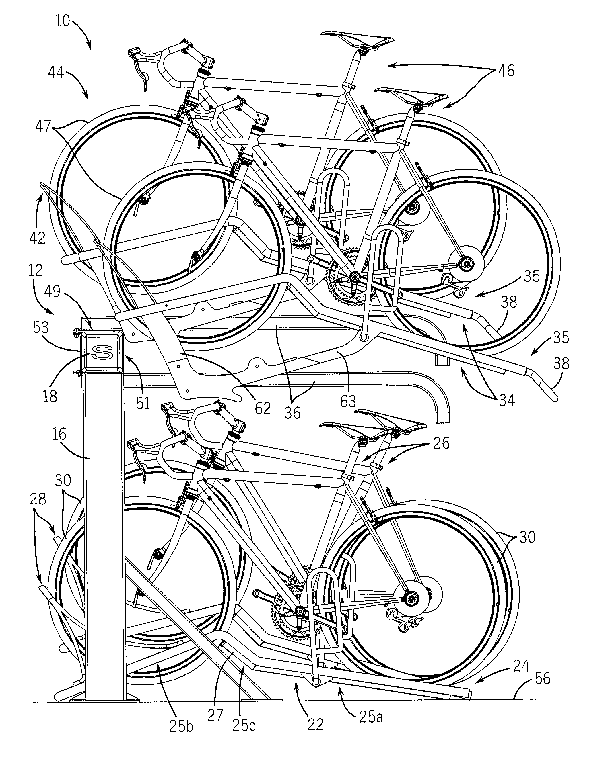
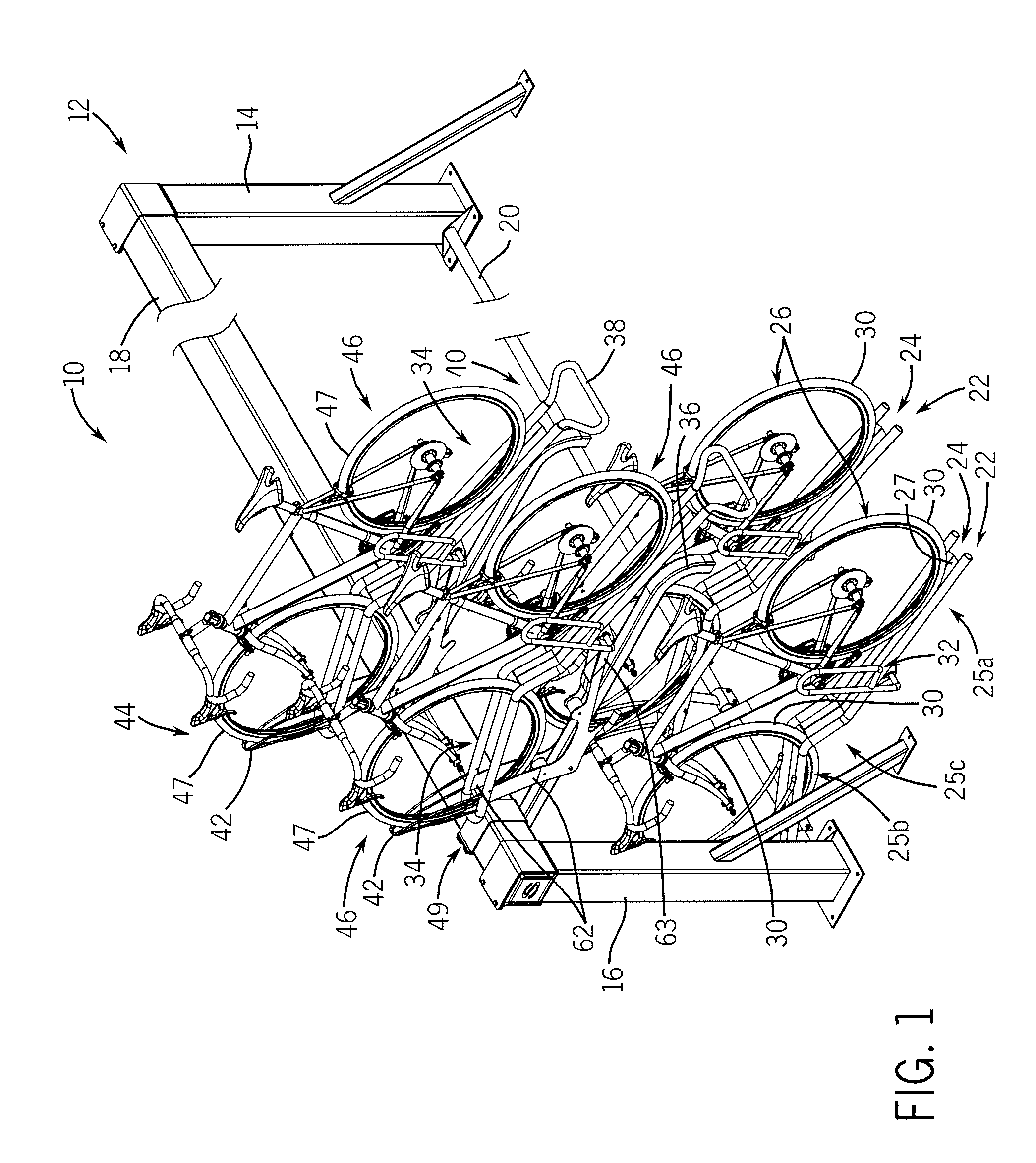
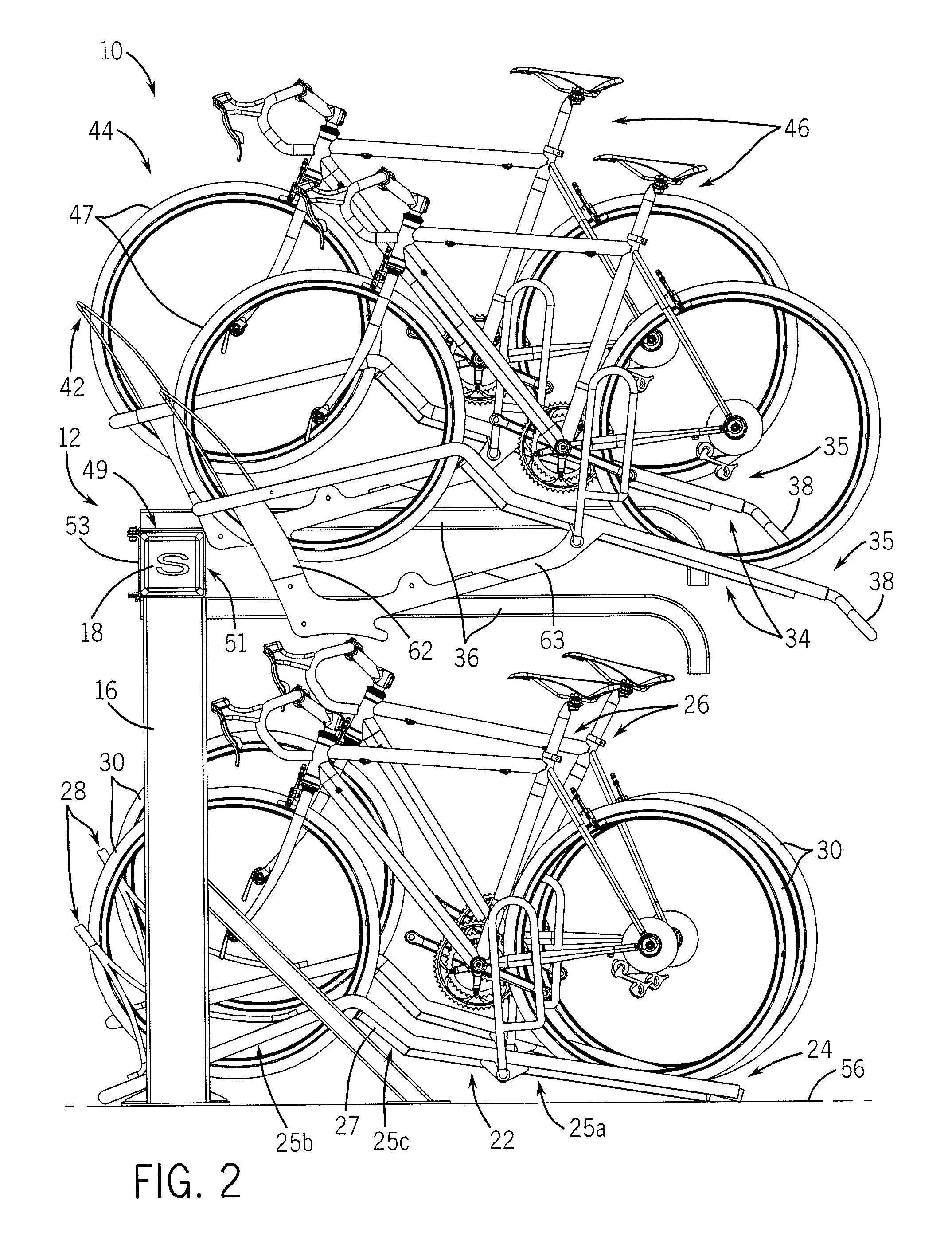
[0021]Referring to FIGS. 1 and 2, a bicycle parking system 10 according to the present invention includes a frame assembly 12 having a pair of end posts 14, 16, and an upper frame member or rail 18 and a lower frame member or rail 20 extending between the end posts 14, 16. A number of lower supports 22 are connected to lower rail 20 of frame assembly 12, and a number of upper supports 34 are connected to upper rail 18. While the drawings illustrate two lower supports 22 and two upper supports 34, it is understood that any desired number of lower supports 22 and upper supports 34 may be located between end posts 14, 16.

[0022]Each lower support 22 forms a trough-shaped guide 24 constructed to receive a pair of wheels 30 associated with a vehicle, such as a bicycle 26, in the trough of the guide 24. Each trough-shaped guide 24 may be formed of a pair of bent, spaced apart tubular members, and defines a rear support area 25a, a front support area 25b, and an angled intermediate area 25c...


PUM


Abstract

A bicycle parking system includes a frame having a number of lower supports and a number of upper supports, each support being constructed to receive a bicycle. The frame includes a slide bar operatively engaged with each of the upper supports. Each slide bar includes a curved end to allow the attached upper support to rotate relative to the slide bar for loading and unloading of the upper support. A spring assembly biases each upper support toward a stored position.

Description


Claims


Application Information

Patent Timeline
Owner SARIS EQUIP LLC
Why Eureka
Try Eureka