
Cross-linked variable piston air suspension

a variable piston and air suspension technology, applied in the direction of shock absorbers, mechanical equipment, transportation and packaging, etc., can solve the problems of packaging and cost perspective disadvantages, and achieve the effects of reducing roll stiffness, facilitating traction, and facilitating traction

Inactive Publication Date: 2011-05-24
ARVINMERITOR TECH
View PDF22 Cites 7 Cited by
  • Summary
  • Abstract
  • Description
  • Claims
  • Application Information

AI Technical Summary

Benefits of technology

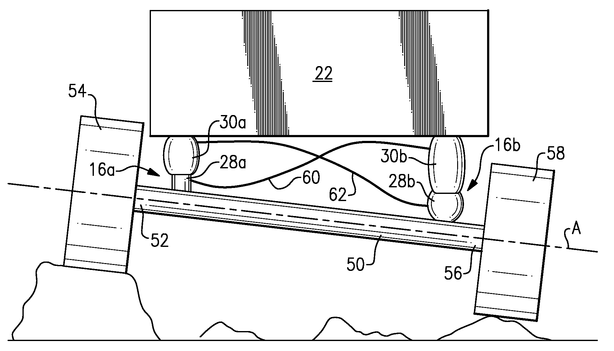
The patent describes an air suspension system for vehicles that allows for improved articulation and traction. The system includes two air spring assemblies that are fluidly cross-linked, meaning they are connected, to allow for controlled air flow between them. The airbags in the assemblies are designed to provide a rolling surface for each other, allowing for smoother movement. The system also includes an active control that can independently control the air supply to each airbag, making it more versatile and efficient. Overall, the system improves the performance and comfort of vehicles.

Problems solved by technology

This is disadvantageous from a packaging and cost perspective.

Method used


Image

  • Cross-linked variable piston air suspension
  • Cross-linked variable piston air suspension
  • Cross-linked variable piston air suspension

Examples


Embodiment Construction

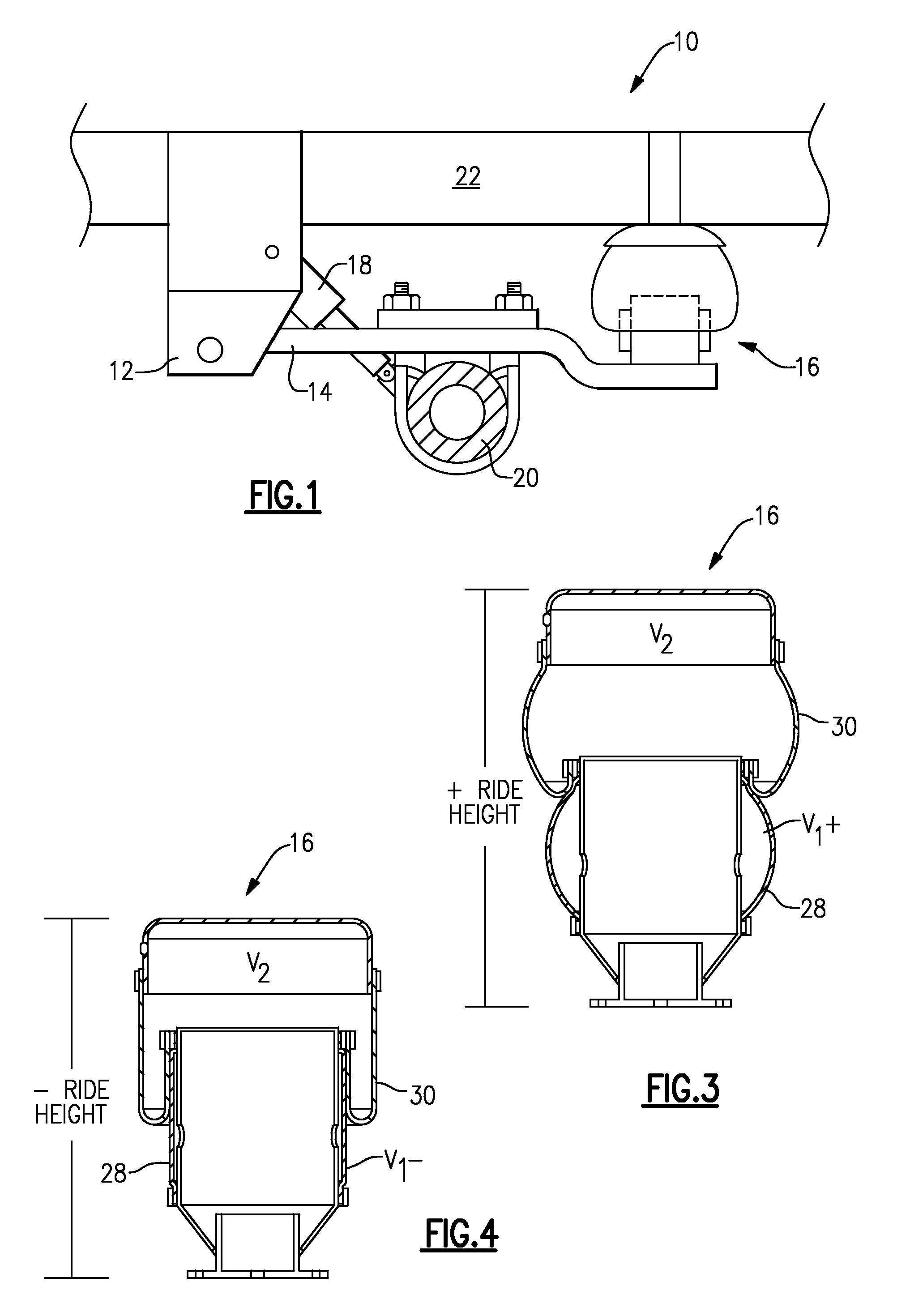
[0014]FIG. 1 illustrates an air suspension system 10 for a vehicle. The air suspension system 10 generally includes a bracket 12, a longitudinal member 14, an air spring assembly 16, a damper 18, and an axle assembly 20. The air suspension system 10 is fixed to a frame or chassis of the vehicle (shown schematically at 22). The longitudinal member 14 could comprise a suspension arm, for example, and the axle assembly 20 could comprise any type of axle, such as a drive axle, non-drive axle, trailer axle, etc. The axle assembly 20 extends between laterally spaced wheels (not shown). It should be understood that the air suspension system 10 includes a longitudinal member 14, an air spring assembly 16, and a damper 18 at each lateral end of the axle assembly 20.

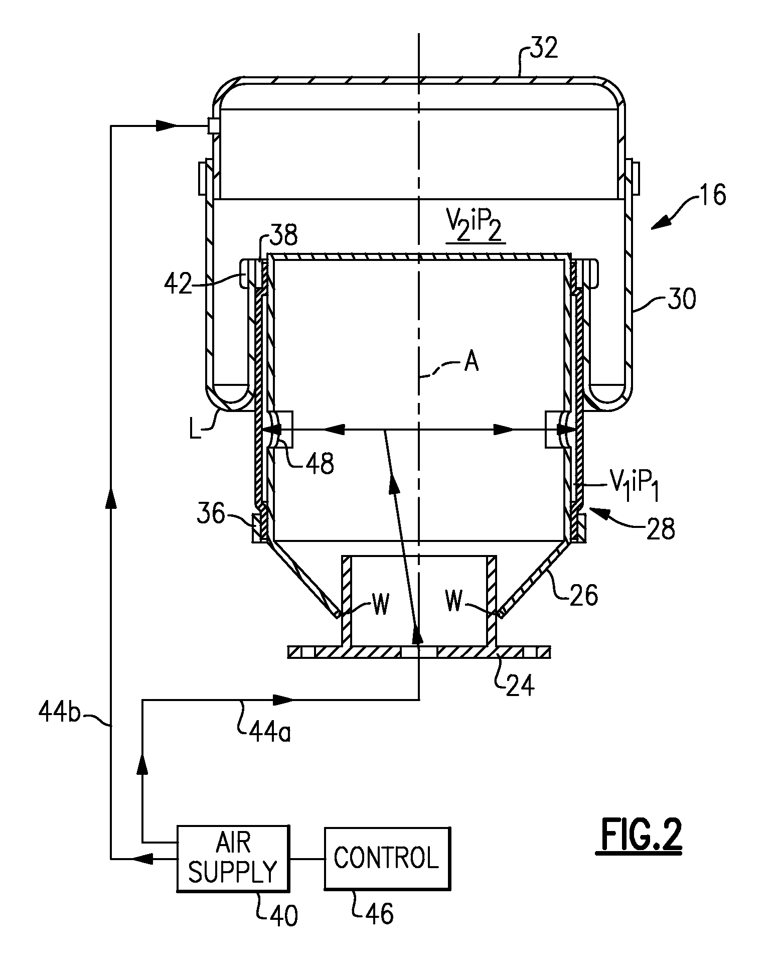
[0015]Referring to FIG. 2, the air spring assembly 16 is illustrated in cross-section. The air spring assembly 16 is defined along a central vertical axis A and includes a lower mount 24 (illustrated schematically), a piston suppo...


PUM


Abstract

An air suspension includes first and second air spring assemblies that each include a piston airbag and a primary airbag. A first fluid connection connects one of a first piston airbag and a first primary airbag of the first air spring assembly to one of a second piston airbag and a second primary airbag of the second air spring assembly. A second fluid connection connects the other of the first piston airbag and the first primary airbag to the other of the second piston airbag and the second primary airbag. Air flow through the first and second fluid connections is passively controlled solely in response to road load inputs to reduce roll stiffness and improve articulation.

Description

TECHNICAL FIELD[0001]This invention generally relates to an air suspension system with cross-linked air spring assemblies.BACKGROUND OF THE INVENTION[0002]Air suspensions utilize air springs to provide desired output characteristics, such as ride comfort and vehicle performance for example. One known active air suspension uses an air spring assembly that includes a primary airbag mounted around a piston airbag such that the piston airbag provides a rolling surface for the primary airbag. A change in piston airbag volume changes an effective piston area of the primary airbag. A relatively small change in the effective piston area provides a change in a spring rate of the air spring assembly. The pressures in the piston airbag and the primary airbag are selectively controlled to provide infinite variation in spring rates without requiring any auxiliary tanks and associated actuators. The smaller volume of the piston airbag relative to the larger volume of the primary airbag permits ra...

Claims


Application Information

Patent Timeline
Patent Type & Authority Patents(United States)
IPC IPC(8): B60G17/052
CPCB60G17/0165B60G17/0485B60G17/0521B60G21/073B60G2500/20B60G2204/82B60G2204/8304B60G2400/0521B60G2202/152
Inventor LLOYD, JEFFREY M.
Owner ARVINMERITOR TECH
Learn More