Screw type liquid ring pump with shaft seal arrangement

a liquid ring pump and screw-type technology, which is applied in the direction of pumps, mechanical equipment, liquid fuel engines, etc., can solve the problems of additional work and motor break down, and achieve the effect of shortening the construction length of the total pump and being easy to assembl

Inactive Publication Date: 2011-05-24
JETS
View PDF26 Cites 8 Cited by
  • Summary
  • Abstract
  • Description
  • Claims
  • Application Information

AI Technical Summary

Benefits of technology

[0006]The present invention provides an improved shaft seal solution which eliminates or at least essentially reduces the problem of leakage to the motor, which is essentially simpler to assemble and which provides essentially a shorter construction length of the total pump and motor solution.

Problems solved by technology

A disadvantage with this solution is that leakage in the shaft seal will result in moisture entering into the bearing and further into the motor housing which, in the worst case, will result in break down of the motor.
Another disadvantage is that the seal arrangement as such and the connection between the pump and the motor is relatively complicated and causes additional work in connection with the mounting and maintenance of the pump.

Method used


Image

  • Screw type liquid ring pump with shaft seal arrangement
  • Screw type liquid ring pump with shaft seal arrangement
  • Screw type liquid ring pump with shaft seal arrangement

Examples


Embodiment Construction

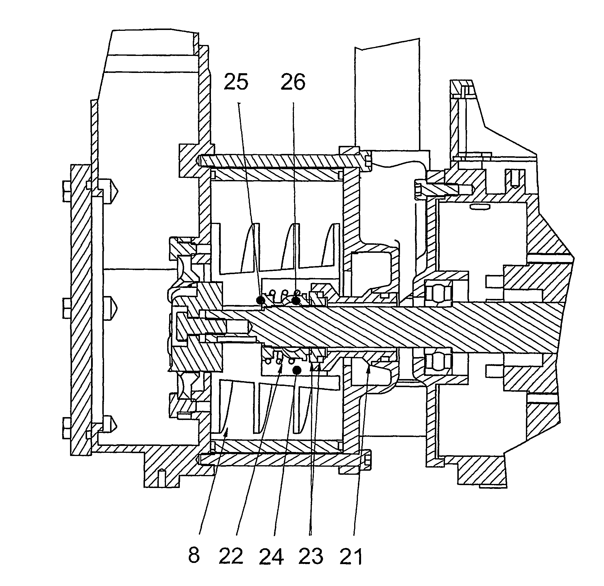
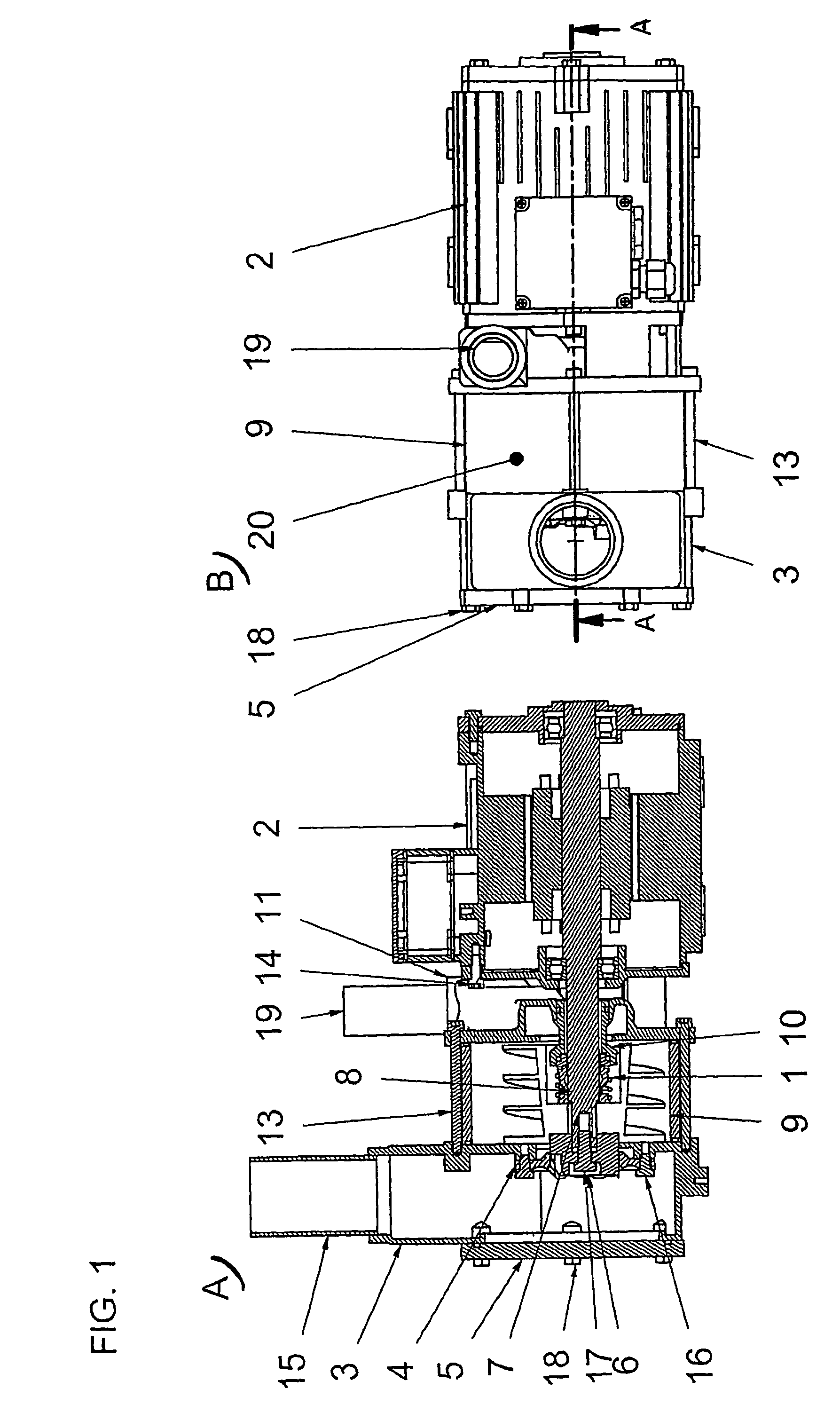
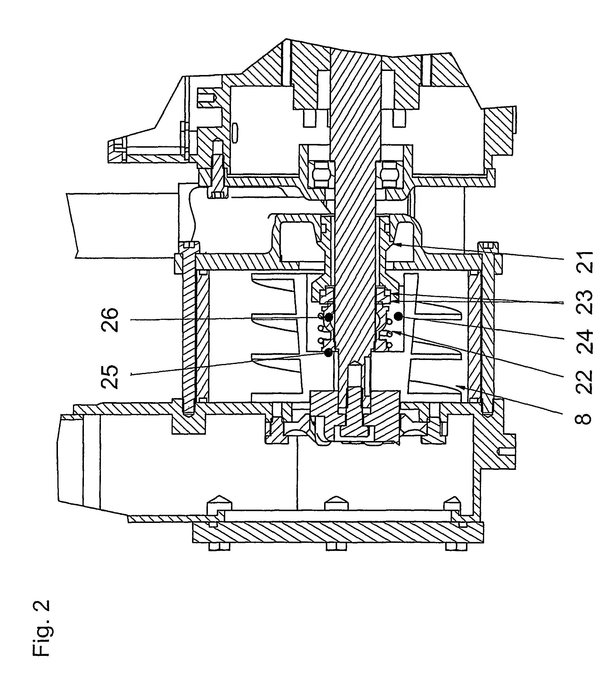
[0011]FIG. 1 shows, as mentioned above, a pump and motor solution according to the invention. It includes a driving unit in the form of a motor, preferably an electric motor 2 and a pump unit 20 in the form of a liquid ring screw pump (with a helical screw rotor 8) built together as an integrated unit. The pump unit, as such, also includes an inlet part 3 with an inlet connection 15, a screw rotor 8 connected at its forward part with a shaft 7 as is common for a motor and pump, a rotor housing 9 and an outlet part or pressure chamber part 11 with an outlet part connection 19. The outlet part is an intermediate piece between the pump 20 and the motor 2 and forms the connection between the two units, whereby the outlet part 19 is connected with the housing for the motor 2 via a screw connection by means of screws 14.

[0012]The main parts of the pump unit 20, i.e., the inlet part 3, the rotor housing 9 and the outlet part 11 are, on the other hand, with an intermediate seal element (not...


PUM


Abstract

Screw type liquid ring pump including a pump housing (9) with an inlet part (3) and an outlet part (11) and rotating helical screw rotor (8) inside the housing. The rotor is connected with a shaft (7) as well as a driving unit in the form of motor, preferably an electric motor (2), whereby the pump (20) with the pump housing (9) represents an elongation of the motor (2) with the motor housing thus representing an integrated or one piece unit. The shaft seal (22, 23) is provided wholly or partially in an annular space (24) provided within the rotor (8), whereby one end of the seal rests against an annular part (25) of the screw rotor provided in the annular space (24) between the rotor and the shaft, and its other end is tightly engaged against an inwardly protruding part (21) at the outlet end of the pump.

Description

BACKGROUND OF THE INVENTION[0001]1. Field of Invention[0002]The present invention relates to a screw type liquid ring pump including a pump housing with an inlet and an outlet and a rotating helical screw rotor inside the housing, the rotor being connected with a shaft and a driving unit in the form of a motor, preferably an electric motor, whereby the pump housing represents an elongation of the motor housing forms an integrated or one-piece unit therewith.[0003]2. Description of Related Art[0004]Liquid ring pumps of the above kind are commonly known where the pump and the driving unit, usually an electric motor, are built together forming a unit. With such a solution, the production is simplified and the costs are reduced, mainly due to the fact that fewer constructional parts are required, such as only one shaft and two shaft bearings, compared to a conventional solution where the pump and rotor are manufactured as two independent units, each with two bearings. The structural len...

Claims


Application Information

Patent Timeline
Patent Type & Authority Patents(United States)
IPC IPC(8): F04C19/00F16J15/00F04C27/00
CPCF04C27/009F04C19/00F04C18/16F04D29/12F04C25/02
Inventor OVSTHUS, EIMUNDOVSTHUS, AKSEL
Owner JETS
Why Eureka
Try Eureka