Focusing optical system for material machining by means of laser radiation and laser machining head with such focusing optical system

A technology for focusing optical systems and laser processing heads, applied in optics, optical components, manufacturing tools, etc., can solve the problems of high mechanical effort, large number of thermal focus shifts, etc., to achieve the effect of mechanical design and simple mechanical design

Pending Publication Date: 2018-10-26
PRECITEC GMBH
View PDF10 Cites 8 Cited by
  • Summary
  • Abstract
  • Description
  • Claims
  • Application Information

AI Technical Summary

Problems solved by technology

[0005] In this case, the disadvantage is that a high mechanical effort is required in the focusing section, since there is a risk of Special requirements for robustness and accessibility
[0009] The movable optics are also located in the collimation section in this case, but the usual thermal problems of laser material processing, such as thermal focus shift, are exacerbated by the large number of optics used

Method used


Image

  • Focusing optical system for material machining by means of laser radiation and laser machining head with such focusing optical system
  • Focusing optical system for material machining by means of laser radiation and laser machining head with such focusing optical system

Examples


Embodiment Construction

[0021] The same elements are designated with the same reference numerals in the figures.

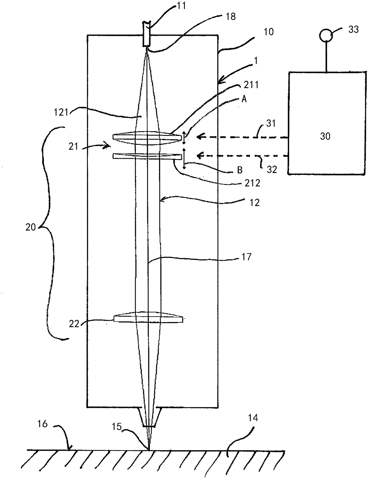
[0022] figure 1 A laser processing head 10 is shown through which a working laser beam 12 supplied via an optical fiber 11 is guided and directed onto a workpiece 14 . The divergent working laser beam 121 output via the optical fiber 11 is focused by means of the focusing optics 20 at the working focal point 15 located on, above or below the surface 16 of the workpiece 14 .

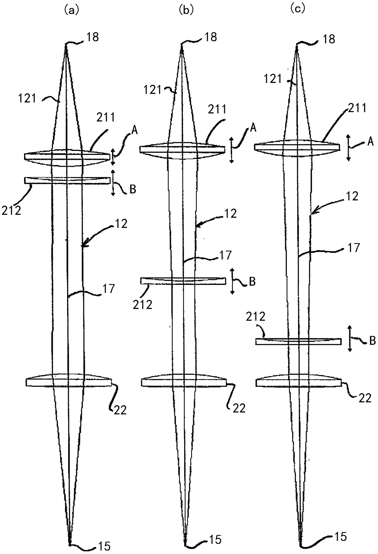
[0023] The focusing optical system 20 includes a collimating optical device 21 and a focusing optical device 22 . The collimating optics 21 consist of a first movable lens or lens group 211 with a positive focal length and a second movable lens or lens group 212 with a negative focal length. Both the first and second movable lenses or lens groups 211, 212 are axially displaceable (as indicated by corresponding arrows) along the optical axis 17 by means of respective actuating drives A, B to thereby adjust the foca...


PUM

PropertyMeasurementUnit
diameteraaaaaaaaaa

Abstract

The invention relates to a focusing optical system (20) for material machining with laser radiation. The system includes a collimator optical device (21) for collimating a divergent working laser beam(121) and a focusing optical device (22) for focusing a working laser beam (12) onto a workpiece (14) to be machined, wherein the collimator optical device (21) comprises a first moving lens or lensgroup (211) having a positive focal length for focusing a working laser beam source (18) into a virtual intermediate focus, and a second moving lens or lens group (212) having a negative focal lengthfor focusing the virtual intermediate focus to infinity. A laser machining head (1) with a housing (10) is also provided, and a working laser beam (12) can be guided to pass through the housing. The focusing optical system (20) according to the invention functions to generate a working focus (15).

Description

technical field [0001] The invention relates to a focusing optics for material processing by means of laser radiation and also to a laser processing head equipped with such a beam shaping optics. Background technique [0002] In the processing of workpieces by means of laser radiation, it is often necessary to adjust the focus position (ie the position of the laser beam focus relative to the laser processing head and / or relative to the workpiece) and the focal spot diameter. This adjustment is necessary, for example, when changing from processing thin sheet metal to thick sheet metal in a laser cutting system. If the focal spot diameter cannot be varied over a sufficiently wide range in this case, the processing optics would have to be replaced, thereby reducing the productivity of the laser processing system. [0003] The following optical systems are known in technical optics as zoom systems by means of which the size of the image can be changed while keeping the position...

Claims


Application Information

Patent Timeline
Patent Type & Authority Applications(China)
IPC IPC(8): B23K26/046B23K26/06G02B27/09
CPCB23K26/046B23K26/0648B23K26/0665G02B19/0052G02B19/0014G02B15/173B23K26/06G02B27/09B23K26/38G02B19/0047
Inventor D·布拉斯奎兹-桑切斯
Owner PRECITEC GMBH
Why Eureka
Try Eureka