Closing unit of a shaping machine

A molding machine and closing force technology, applied in the field of mold clamping units, can solve the problems of increasing movable parts, reducing the accuracy of the half movement of the open-loop control or closed-loop control nut, etc. Effect

Active Publication Date: 2016-12-21
ENGEL AUSTRIA
View PDF5 Cites 9 Cited by
  • Summary
  • Abstract
  • Description
  • Claims
  • Application Information

AI Technical Summary

Problems solved by technology

If an attempt is made to orient the drive laterally by means of a steering gear, the number of movable parts necessarily increases and the accuracy of the open-loop or closed-loop control of the movement of the nut halves is reduced due to unavoidable transmission gaps

Method used


Image

  • Closing unit of a shaping machine
  • Closing unit of a shaping machine
  • Closing unit of a shaping machine

Examples


Embodiment Construction

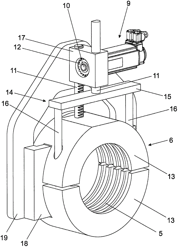
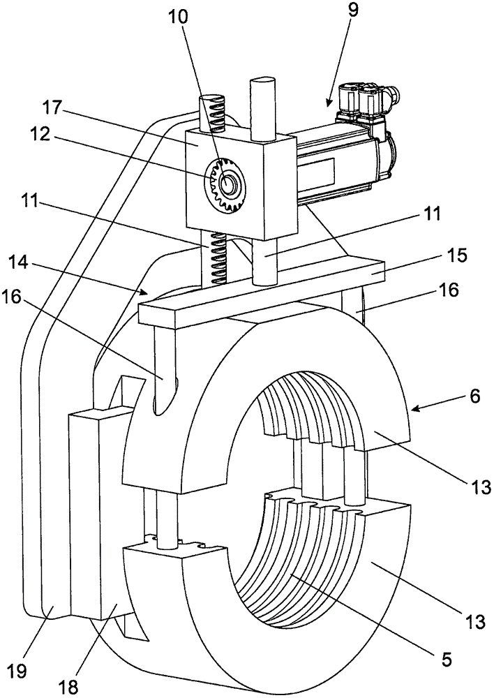
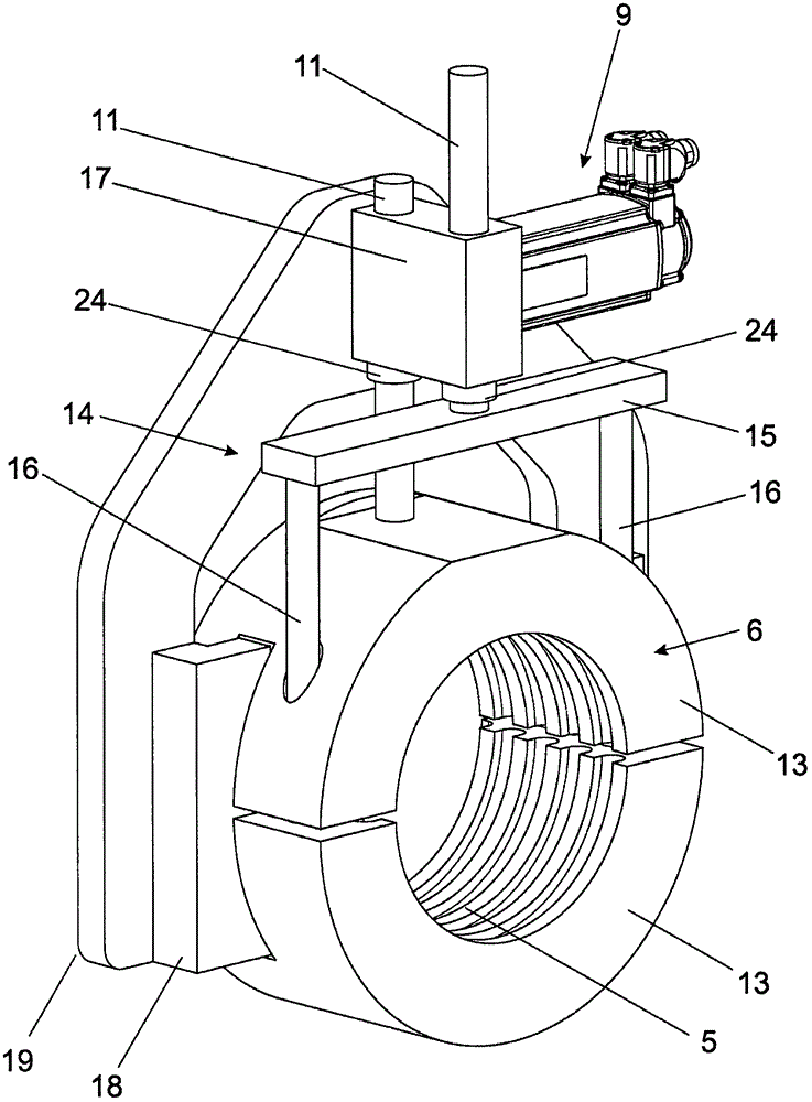
[0030] figure 1 A split nut 6 is shown, the halves 13 of which are each connected to a toothed rack 11 . The rack 11 is driven by the shaft 10 through the meshing portion 8 with the gear 12 . The shaft 10 is rotated here by the servomotor 9 . It can be seen that the lower half 13 of the union nut 6 in the figure is connected to the corresponding toothed rack 11 via a bypass element 14 . The circumvention element 14 basically comprises a bridge element 15 and two rod elements 16 . The rod 16 partially passes through the upper half 13 of the union nut 6 in the figure. This produces an additional guidance of the upper half 13 of the union nut 6 . A gear 12 cooperating with a toothed rack 11 via a toothing 8 is arranged in a housing 17 . Housing 17 is fixed on flange 19 . Flange 19 is connected with the piston member 23 of closing power cylinder or is fixed on it (see also Figure 5 ).

[0031] Furthermore, the flange 19 is connected to a guide 18 which cooperates with a r...


PUM


Abstract

A closing unit of a shaping machine includes a moveable clamping plate, a push rod connected to the moveable clamping plate and having an outside profile, a divided locking nut provided with an inside profile, and a closing force mechanism for acting on the moveable mold clamping plate with a closing force. The push rod is lockable in a closed position of the locking nut by the cooperation of the inside profile and the outside profile with the closing force mechanism. For displacement of the locking nut between an opened and the closed position, a rotary drive is provided for rotation of a shaft, and at least one toothed rack cooperates with the shaft by way of a tooth arrangement and is connected to the locking nut.

Description

technical field [0001] The invention relates to a clamping unit of a molding machine having the features of the preamble of claim 1 . Background technique [0002] This type of clamping unit has a movable clamping plate, a pressure bar with an external profile connected to the movable clamping plate, a split lock nut with an internal profile and a Closing force mechanism for clamping plates to apply closing force. [0003] In this case, the pressure rod is locked with the closing force mechanism in the closed position of the union nut by the cooperation of the inner contour and the outer contour. [0004] A clamping unit of this type is known, for example, from AT 13625 U1. Here, the nut halves are moved by means of an eccentric fastened to the driven shaft. It should be improved that the shaft and thus the drive must be oriented parallel to the longitudinal axis of the pressure rod in order to prevent an asymmetric introduction of forces into the split nut (danger of jam...

Claims


Application Information

Patent Timeline
Patent Type & Authority Applications(China)
IPC IPC(8): B29C33/22
CPCB29C45/6728B22D17/26B29C45/6707B29C2045/664B29C33/22
Inventor F·迪尔奈德S·埃皮希H·维辛格
Owner ENGEL AUSTRIA
Why Eureka
Try Eureka