
Cooling device for fuel cell

a fuel cell and cooling device technology, applied in lighting and heating apparatus, multi-stage water/sewage treatment, separation processes, etc., can solve the problems of deterioration of the ion removal effect of the ion removal filter, a lot of replacement work,

Active Publication Date: 2011-05-24
NISSAN MOTOR CO LTD
View PDF62 Cites 8 Cited by
  • Summary
  • Abstract
  • Description
  • Claims
  • Application Information

AI Technical Summary

Benefits of technology

[0007]An object of the present invention is to provide a cooling device for a fuel cell which enables easy replacement work of a filter cartridge.
[0008]Another object of the present invention is to provide a cooling device for a fuel cell which prevents a cooling liquid from flowing over a cooling liquid circulation passage for replacement work of a filter cartridge.

Problems solved by technology

In the event of replacing a filter cartridge, it is necessary to in advance discharge the cooling liquid from a cooling liquid circulation passage or close passages before and after the ion removal filter to prevent leak of the cooling liquid, which requires a lot of labor for the replacement work.
However, a part of the cooling liquid is flown out through the air vent, possibly causing deterioration of an ion removal effect by the ion removal filter.

Method used


Image

  • Cooling device for fuel cell
  • Cooling device for fuel cell
  • Cooling device for fuel cell

Examples


Embodiment Construction

[0015]A selected embodiment of the present invention will now be explained with reference to the drawings.

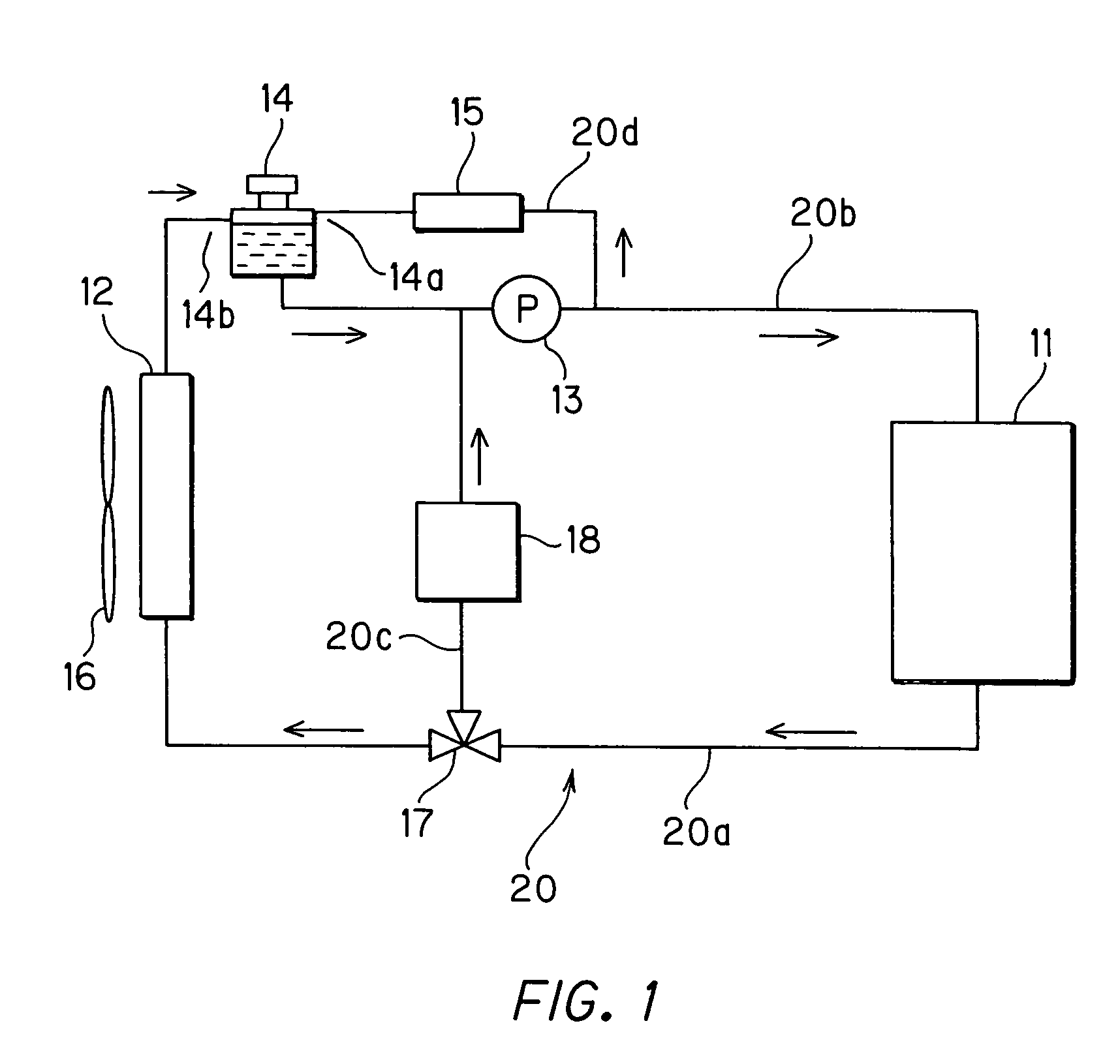
[0016]FIG. 1 shows a schematic construction of a cooling system for a fuel cell to which the present invention is applied.

[0017]In FIG. 1, a fuel cell stack 11 generates power by supplying oxygen and hydrogen and a cooling liquid circulation passage 20 is disposed where a pure water or ethylene glycol representative of a glycolic antifreezing liquid is circulated as a cooling liquid to cool the fuel cell stack 11 heated in generating the power.

[0018]The cooling liquid circulation passage 20 is equipped with a radiator 12 to radiate heat in the cooling liquid, an electrically operated pump 13 to circulate the cooling liquid, a reservoir tank 14 to reserve the cooling liquid, an ion removal filter 15 to remove ions contained in the cooling liquid, a three-way valve 17 to change a flowing path of the cooling liquid in response to a temperature of the cooling liquid, and a heat exch...


PUM

PropertyMeasurementUnit
conductivityaaaaaaaaaa
poweraaaaaaaaaa
temperatureaaaaaaaaaa

Abstract

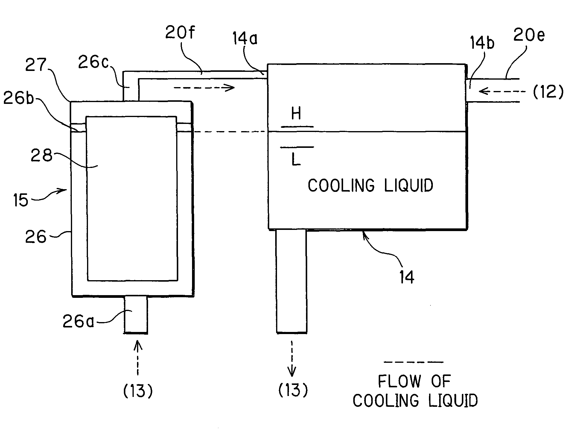
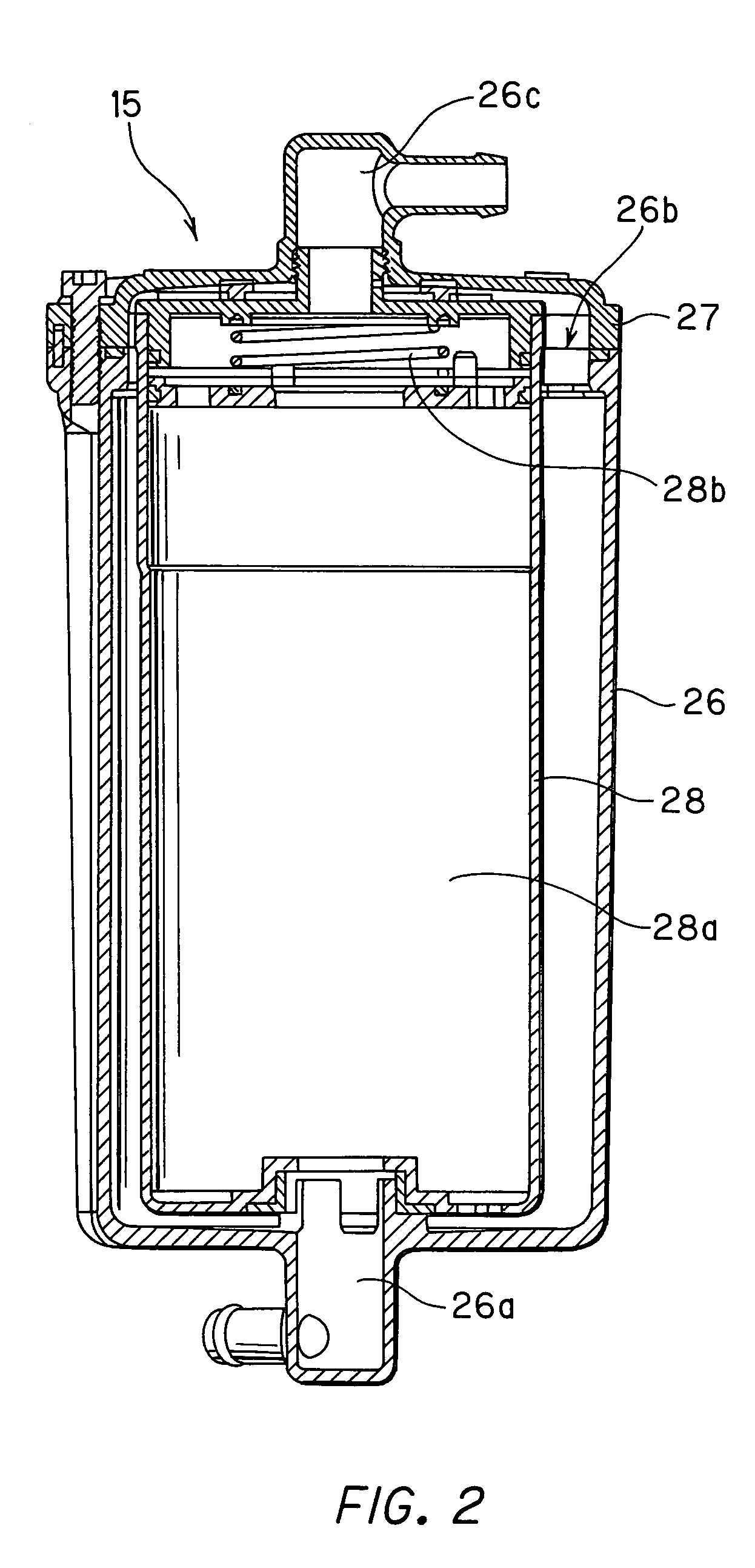
A cartridge-type ion removal filter 15 to remove ions from the cooling liquid in the cooling liquid circulation passage 20 is disposed in the middle of a cooling liquid circulation passage 20 to circulate the cooling liquid between a fuel cell stack 11 and a radiator 12. The ion removal filter 15 is disposed in the cooling liquid circulation passage so that an opening 26b of a vessel main body 26 is in a higher position than the highest level “H” of the cooling liquid in the reservoir tank 14.

Description

BACKGROUND OF THE INVENTION[0001]1. Field of the Invention[0002]The present invention relates to a cooling device for a fuel cell which circulates a cooling liquid to a fuel cell stack and in particular, to an improvement of an ion removal filter of the same.[0003]2. The Related Art of the Invention[0004]As shown in Japanese Patent Publication No. 2001-35519 A, there is known a cooling device with a cartridge-type ion removal filter which is disposed in a circulation passage for a cooling liquid in a fuel cell mounted on a movable body (for example, a vehicle). It is preferable that the cooling liquid used in the fuel cell has a low conductivity whereby an electrical current does not flow through the cooling liquid easily. Therefore, conductivity of the cooling liquid is always maintained below a predetermined value due to removing the ions from the cooling liquid through the ion removable filter.SUMMARY OF THE INVENTION[0005]In the event of replacing a filter cartridge, it is neces...

Claims


Application Information

Patent Timeline
Patent Type & Authority Patents(United States)
IPC IPC(8): B01D15/04B01D27/02C02F1/42F25B27/00H01M8/04H01M8/12
CPCH01M8/04029H01M8/04044Y02E60/50
Inventor TAKEMOTO, SHINICHIRO
Owner NISSAN MOTOR CO LTD
Learn More