
Display panel, display apparatus and driving method thereof

a technology of display apparatus and display panel, which is applied in the direction of instruments, static indicating devices, etc., can solve the problems of increasing the design cost of driving ics, increasing parasitic capacitance and parasitic impedance, and increasing the design cost, so as to reduce the quantity of gate driving circuits and the layout space

Inactive Publication Date: 2011-05-24
CHUNGHWA PICTURE TUBES LTD
View PDF10 Cites 3 Cited by
  • Summary
  • Abstract
  • Description
  • Claims
  • Application Information

AI Technical Summary

Benefits of technology

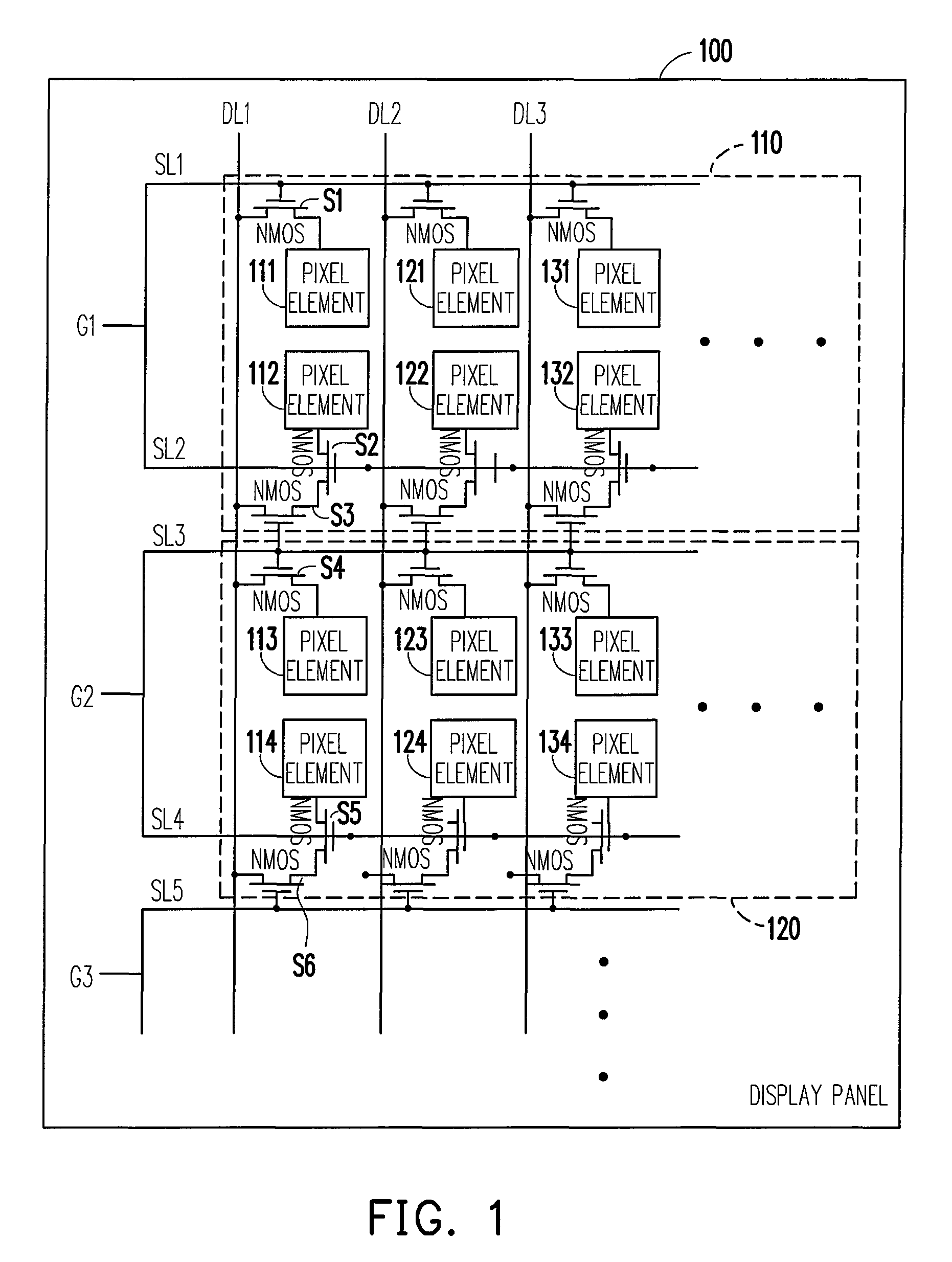
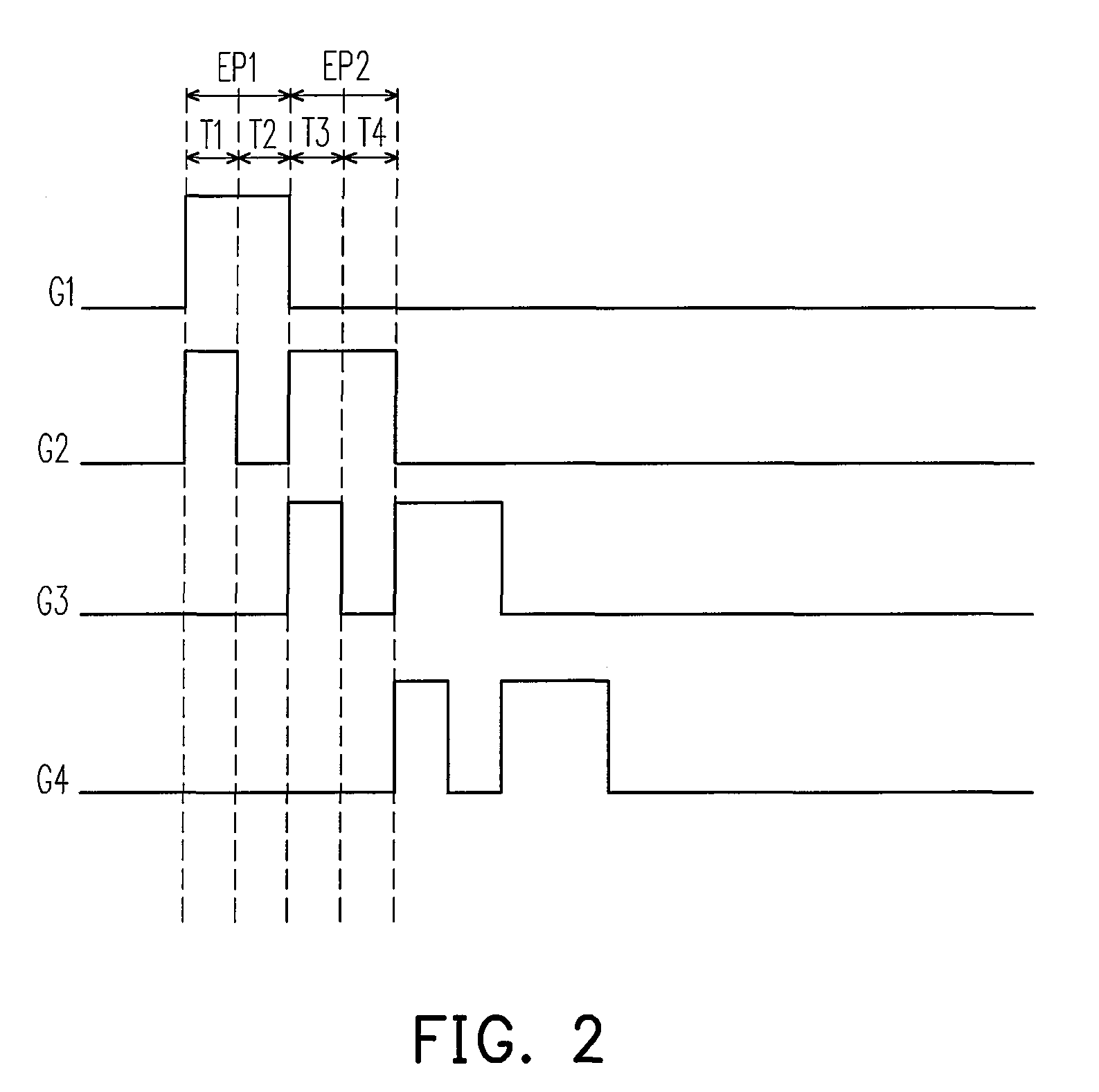
"The present invention provides a display panel that can reduce the number of gate control signals needed to control more scan lines, thereby reducing the quantity of gate driving circuits and the layout space of the fan out area. The display panel includes multiple scan lines that can be simultaneously scanned using a renewed scanning manner. The driving method includes sequentially providing N gate control signals to the scan units and simultaneously enabling the i-th gate control signal and the (i+1)-th gate control signal to scan the pixel elements corresponding to the first scan line and the second scan line of the i-th scan unit and to output the pixel data corresponding to the second scan line to the pixel elements corresponding to the first scan line and the second scan line. The present invention utilizes a gate control signal to interactively control scan lines, reducing the quantity of gate control signals needed to control more scan lines."

Problems solved by technology

Meanwhile, more gate driving ICs are needed to provide gate control signals, which result in an increasing design cost of the driving ICs.
Thus, the fan out area served for connecting the gate terminals and the scan lines (or termed as gate lines) in the panel would become more tight and congested with an increasing number of scan lines, which would increase parasitic capacitance and parasitic impedance.
However, to reduce the influence of parasitic capacitance and parasitic impedance, a sufficient space for wiring of signal and the layout thereof is needed; more tight the layout of a circuit is, the more sensitive the circuit is to the generated parasitic capacitance to affect the display quality.
US2006 / 0022202 provides a scheme to reduce the number of gate control signals by half by using a control circuit, but it requires an additional control circuit to perform the switching of driving signals, which results in an increasing design cost.

Method used


Image

  • Display panel, display apparatus and driving method thereof
  • Display panel, display apparatus and driving method thereof
  • Display panel, display apparatus and driving method thereof

Examples


Embodiment Construction

[0021]Reference will now be made in detail to the present preferred embodiments of the invention, examples of which are illustrated in the accompanying drawings. Wherever possible, the same reference numbers are used in the drawings and the description to refer to the same or like parts.

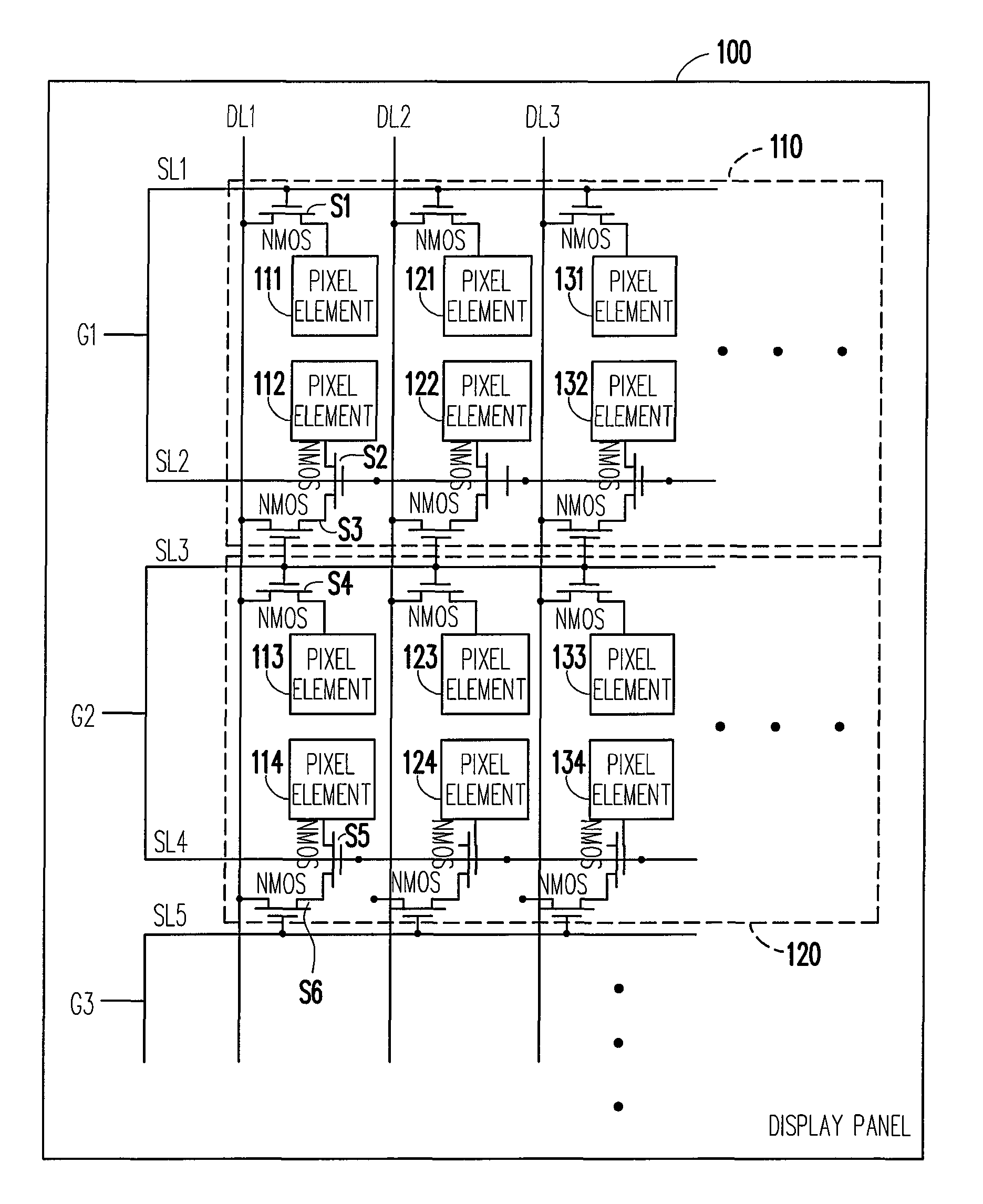
[0022]FIG. 1 is a display panel diagram according to an embodiment of the present invention. A display panel 100 includes a plurality of scan units, however in FIG. 1, only scan units 110 and 120 are illustrated to exemplarily depict the spirit of the present invention. Each of the scan units includes two scan lines and each scan line corresponds to a plurality of pixel elements. The plurality of pixel elements of the display panel 100 is arranged, for example, in an array, and each pixel element corresponds to a scan line and a data line. For example, a first pixel element 111 (pixel element 111 for short) corresponds to a data line DL1 and a first scan line SL1. During scanning a pixel element, i.e...


PUM


Abstract

A display panel, a display apparatus and the driving method thereof are provided. The gate control signals can interactively control more number of scan lines by disposing corresponding switches between the adjacent scan lines in the display panel, wherein every two scan lines correspond to a gate control signal, so as to reduce the number of the gate driving ICs and the layout space required by the fan out area in the display panel.

Description

CROSS-REFERENCE TO RELATED APPLICATION[0001]This application claims the priority benefit of Taiwan application serial no. 96107471, filed Mar. 5, 2007. All disclosure of the Taiwan application is incorporated herein by reference.BACKGROUND OF THE INVENTION[0002]1. Field of the Invention[0003]The present invention generally relates to a display panel, and more particularly, to a thin film transistor liquid crystal display panel (TFT-LCD), a display apparatus and the display method thereof which are capable of reducing the amount of gate control signals.[0004]2. Description of Related Art[0005]Along with the high resolution development tendency of a TFT-LCD, more scan lines are required to be disposed on a display panel. Meanwhile, more gate driving ICs are needed to provide gate control signals, which result in an increasing design cost of the driving ICs.[0006]In the prior art, since the gate control signals and the scan lines are configured in one-to-one manner, the gate driving ci...

Claims


Application Information

Patent Timeline
Patent Type & Authority Patents(United States)
IPC IPC(8): G09G3/36
CPCG09G3/3659G09G2310/0205
Inventor TSOU, YUAN-HSINLIU, WEN-HSIUNGHE, CHIEN-KUO
Owner CHUNGHWA PICTURE TUBES LTD
Learn More