Imaging apparatus and correction method of image data

a technology of image data and correction method, applied in the field of image data correction method, can solve the problems of not being able to always include random noise in image data, not being able to prefer, and not being able to eliminate new noise, etc., and achieve the effect of reducing nois

Inactive Publication Date: 2011-05-24
PANASONIC CORP
View PDF24 Cites 10 Cited by
  • Summary
  • Abstract
  • Description
  • Claims
  • Application Information

AI Technical Summary

Benefits of technology

[0011]It is hence an object of the invention to present an imaging apparatus capable of reducing noise caused by random noise contained in a correction signal for correcting image data, that is, noise newly generated on correction of mage data.

Problems solved by technology

The fixed pattern noise is noise which is caused by fluctuation of characteristic of each pixel and generated when the image data is displayed on screen.
However, the above method may not be preferable because the random noise is also subtracted thus causing new noise.
More specifically, if random noise is included in black level information, random noise may not be always included in the image data.
When random noise is included in the black level information, noise is subtracted from the image data potentially not including the noise, and new noise may be generated by subtraction.

Method used


Image

  • Imaging apparatus and correction method of image data
  • Imaging apparatus and correction method of image data
  • Imaging apparatus and correction method of image data

Examples


first embodiment

1-1 Configuration of Imaging Apparatus

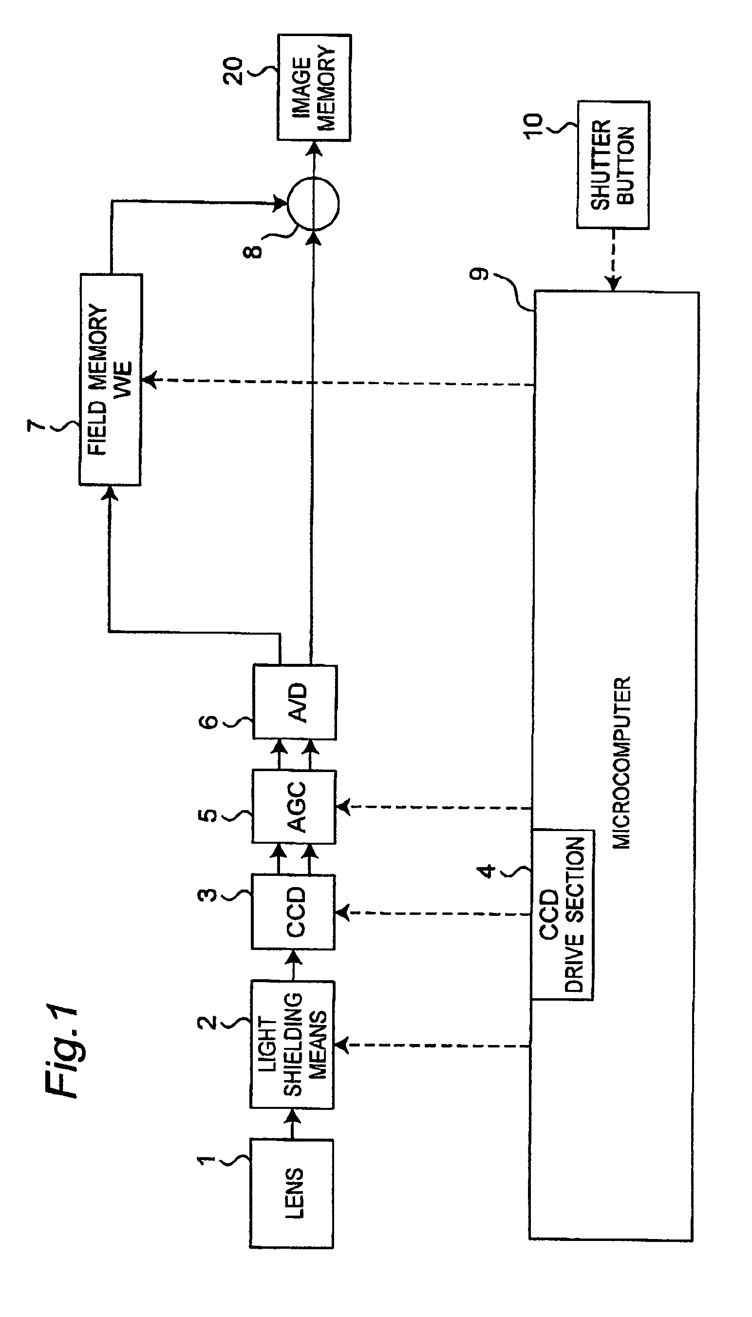
[0068]FIG. 1 is a block diagram of configuration of imaging apparatus in the first embodiment of the invention.

[0069]The imaging apparatus converts an optical signal of an image collected by a lens 1 into an electrical signal by a CCD image sensor 3 to generate image data. The optical signal collected by the lens 1 can be shielded (light-shielded) by a light shielding means 2. The light shielding means 2 is, for example, a mechanical shutter. The generated image data is put into an automatic gain control (AGC) 5 in which the gain is adjusted, and is further sent into an A / D converter 6 to be digitized. A field memory 7 stores a correction signal. A subtractor 8 subtracts the correction signal stored in the field memory 7, from the image data digitized by the A / D converter 6. The image data thus coming out from the subtractor 8 has been deprived of transfer noise component by the correction signal, and is hence high in image quality. The image da...

second embodiment

2-1 Outline of Imaging Apparatus

[0106]The imaging apparatus in the second embodiment of the invention generates transfer fixed noise component of specific size in vertical direction of image, and eliminates such noise by using correction signal for one line. In the first embodiment, one field of data is used as a correction signal. But in the second embodiment, one line of data is used, and thus the storage capacity of storage means for storing correction signal can be further smaller.

2-2 Configuration of Imaging Apparatus

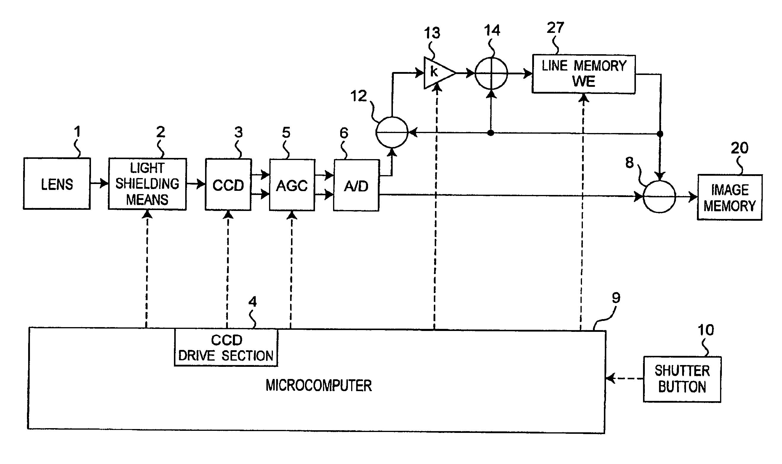
[0107]FIG. 6 is a block diagram of configuration of imaging apparatus in this embodiment. What differs mainly from the configuration shown in FIG. 1 lies in the provision of a line memory 27 and IIR type low pass filter for providing the output of the line memory 27. This low pass filter includes a subtractor 12, a multiplier 13, an adder 14, and the line memory 27, and passes low frequency component of a dummy signal. The low pass filter has the transmission funct...

third embodiment

3-1 Outline of Imaging Apparatus

[0124]The imaging apparatus in the first or second embodiments is intended to correct regardless of temperature or gain of AGC 5. By contrast, the imaging apparatus in this embodiment determines whether or not to correct depending on the temperature and / or gain of AGC 5.

[0125]The value of transfer fixed noise component varies with temperature of the CCD image sensor 3, or magnitude of gain to the output of the CCD image sensor 3. At high temperature or large gain, the value of transfer fixed noise component is large. Herein, the large gain is a case of imaging at high sensitivity. In such a case, the transfer fixed noise component is large, and the necessity of correction for eliminating it is higher. On the other hand, when the temperature is low or the gain is small, the value of transfer fixed noise component is also small. In this case, correction may not be needed. If attempted to correct even in such case, noise may be newly generated or other s...


PUM


Abstract

An imaging apparatus is provided for reducing noise which is derived from random noise contained in a correction signal used for correcting an image data and is newly generated on correction of the image data. The imaging apparatus drives vertical transfer registers with no signal charge from photoelectric transducers read out to the vertical transfer registers to obtain and store a correction signal into a field memory. The apparatus subtracts the correction signal from the image data by a subtractor.

Description

TECHNICAL FIELD[0001]The present invention relates to an imaging apparatus having a function of reducing fixed pattern noise from image data generated in a photoelectric transducer and obtained through a vertical transfer register, and a denoising method thereof, and more particularly to denoising of fixed pattern noise derived from electric charge generated in the vertical transfer register.RELATED ART[0002]Hitherto, as the imaging apparatus and method for reducing noise generated in CCD image sensor, for example, the technology disclosed in patent document 1 has been known. As disclosed in the patent document 1(**), a subject image is projected by CCD image sensor to obtain image data, and a vertical transfer register is driven without emitting light to the CCD image sensor to obtain black level information, and the image data is corrected by subtracting the black level information from the image data.[0003]In this prior art, by driving the vertical transfer register without emitt...

Claims


Application Information

Patent Timeline
Patent Type & Authority Patents(United States)
IPC IPC(8): H04N5/217H04N9/64H04N5/225H01L27/00H04N5/374H04N5/3745
CPCH04N5/365H04N5/3595H04N25/625H04N25/67
Inventor TANIZOE, YUKIHIROYAMAMOTO, YASUTOSHIOKABE, YOSHIMASAFUNAKOSHI, HIROMASA
Owner PANASONIC CORP
Why Eureka
Try Eureka