Optical-fiber-characteristic measuring device and optical-fiber-characteristic measuring method

a measuring device and optical fiber technology, applied in the direction of optical apparatus testing, instruments, structural/machine measurement, etc., can solve the problems of increasing noise sb>2/b>, insufficient method for application, long time, etc., to reduce noise, reduce noise, and extend the measurement range

Active Publication Date: 2011-05-24
THE UNIV OF TOKYO +1
View PDF8 Cites 11 Cited by
  • Summary
  • Abstract
  • Description
  • Claims
  • Application Information

AI Technical Summary

Benefits of technology

According to the optical-fiber-characteristic measuring apparatus of the first aspect of the invention, and the optical-fiber-characteristic measuring method of the seventh aspect of the invention, the intensity modulating means perform intensity modulation in synchronization with frequency modulation performed on light from the light source unit, so that the intensity of the output light can be increased or reduced at a specific frequency, thereby appropriately adjusting the spectrum distribution of the output light. Therefore, a noise spectrum shape generated at a position other than a correlation peak position and spreading over the frequency axis can be adjusted, and the peak frequency of the Lorentz spectrum generated at the correlation peak position can be precisely measured, and the measurement range can be extended.
According to the optical-fiber-characteristic measuring apparatus of the second aspect of the invention, and the optical-fiber-characteristic measuring method of the eighth aspect of the invention, it is possible to improve the intensive deflection of the intensity of the output light in the vicinity of the upper end and the lower end of the frequency of the output light in association with the variation of the frequency of the output light from the light source. Therefore, the peak of the Lorentz spectrum can be maintained larger than the peak of the background spectrum, and even if a large strain is applied, the value there can be correctly measured.
According to the optical-fiber-characteristic measuring apparatus of the third aspect of the invention, and the optical-fiber-characteristic measuring method of the ninth aspect of the invention, even in a case where no strain of the measurement-target optical fiber is present or a strain is little, the peak of the Lorentz spectrum can be made larger than the peak of the background spectrum, and regardless of the strain amount of the measurement-target optical fiber, a strain can be measured precisely.
According to the optical-fiber-characteristic measuring apparatus of the fifth aspect of the invention and the optical-fiber-characteristic measuring method of the eleventh aspect of the invention, the intensity of the output light can be adjusted in accordance with the frequency thereof by the inherent filtering characteristic of the optical filter, and the noise reduction and the extension of the measurement range can be easily realized without a synchronization signal from the light source unit.
According to the optical-fiber-characteristic measuring apparatus of the sixth aspect of the invention and the optical-fiber-characteristic measuring method of the twelfth aspect of the invention, by merely changing the frequency modulation waveform of the output light to a waveform other than a sinusoidal wave using the signal generator, the spectrum distribution of the output light can be appropriately adjusted like the case where intensity modulation is performed on the output light, thereby realizing noise reduction and extension of the measurement range.

Problems solved by technology

According to such a method of measuring time regions by light pulses, however, the measurement time is long (taking several minutes to ten minutes), and the spatial resolution is limited (maximum: 1 m), so that the method is insufficient for an application where various constructions are dynamically managed.
According to the foregoing device and method which measure the distribution of characteristics like strains of the measurement-target optical fiber FUT, the longer the measurement-target optical fiber FUT becomes, the wider the measurement range dm must be extended, resulting in an integration of unnecessary components weakened at respective positions other than the correlation position, thus increasing the noise S2.
Accordingly, as particularly shown in the bottom part of FIG. 23, at a position where the shift frequency of the accrual signal S1 due to a strain is large, the signal peak thereof becomes smaller than the level of the noise S2, so that the measurement of the distribution of strains becomes difficult.

Method used


Image

  • Optical-fiber-characteristic measuring device and optical-fiber-characteristic measuring method
  • Optical-fiber-characteristic measuring device and optical-fiber-characteristic measuring method
  • Optical-fiber-characteristic measuring device and optical-fiber-characteristic measuring method

Examples


first embodiment

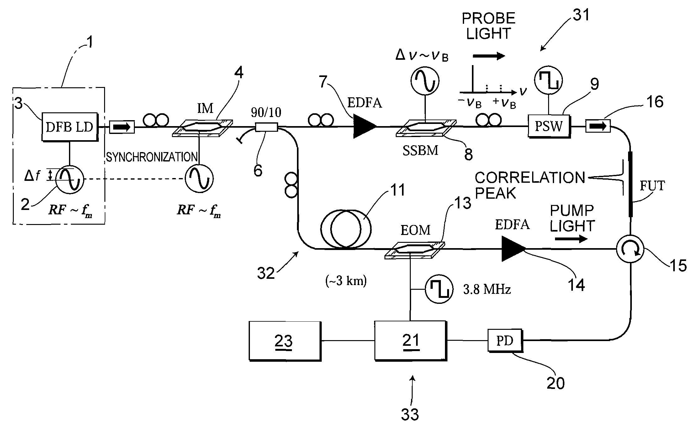
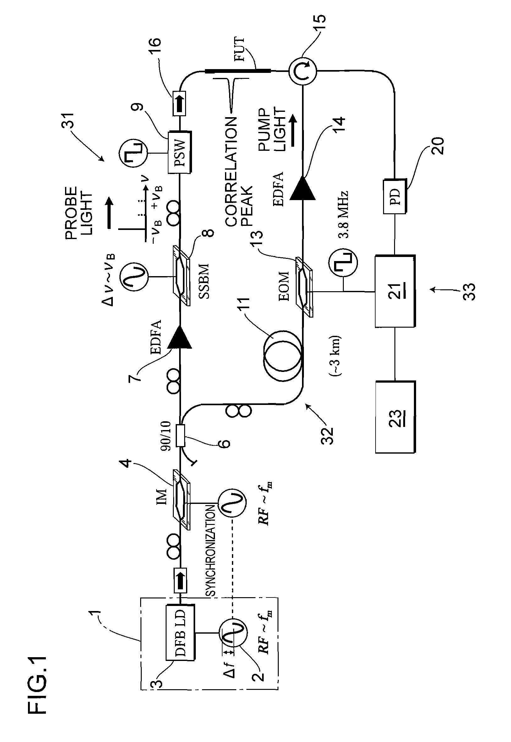
FIG. 1 shows an optical-fiber-characteristic measuring apparatus according to the In the figure, reference numeral 1 denotes a light source which comprises a signal generator 2 and a semiconductor laser 3. A possible semiconductor laser 3 is, for example, a distributed feedback laser diode (DFB LD) which is small in size and emits a laser light having a narrow spectrum width. The signal generator 2 is for outputting a desired modulated signal as an injected current to the semiconductor laser 3 to perform sinusoidal frequency modulation (including phase modulation) on continuous laser light emitted from the semiconductor laser 3.

Reference numeral 4 denotes an optical intensity modulator (IM) as intensity modulating means for performing intensity modulation on output light from the semiconductor laser 3 in synchronization with the frequency modulation performed on the semiconductor laser 3. The optical intensity modulator 4 has a function of receiving a synchronization signal corresp...

second embodiment

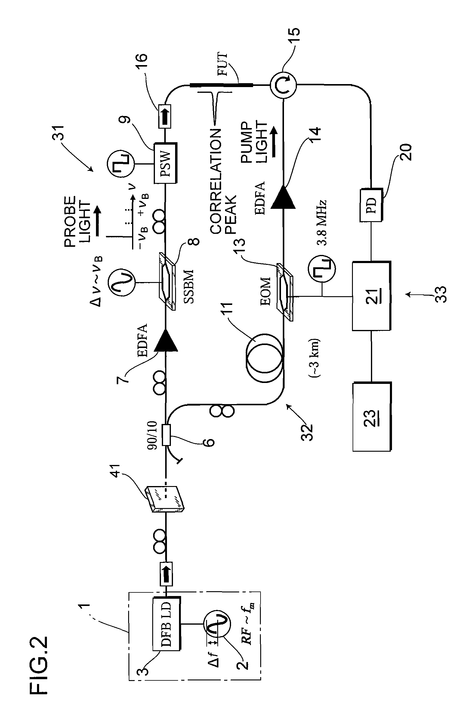
FIG. 2 shows an apparatus and an optical filter 41 having an appropriate transmission spectrum characteristic is disposed in the optical path of the output light from the light source 1 instead of the optical intensity modulator 4. In this case, the optical filter 41 substantially performs intensity modulation as the intensity modulating means in synchronization with the frequency modulation performed on the output light from the light source 1, thereby appropriately adjusting the spectrum distribution of the output light. In a case where the optical filter 41 is used, the output light can be intensively adjusted in accordance with the frequency thereof because of the filtering characteristic of the optical filter 41, the synchronization signal from the signal generator 2 becomes unnecessary, and the reduction of the noise S2 and the extension of the measurement range dm remarkably easily achieved.

third embodiment

Further, as another structure of the intensity modulating means, a direct-modulation-scheme type signal generator 51 which performs frequency modulation on the output light from the light source 1 with repeated waveforms other than a sinusoidal wave instead of the external-modulation-scheme type optical intensity modulator 4. FIG. 3 shows such an example as a third embodiment, and the signal generator 51 has a function of performing frequency modulation on the output light from the semiconductor laser 3 with a triangular repeated waveform for example.

FIG. 14 shows frequency modulation waveforms for a case where the output light is subjected to frequency modulation with a conventional sinusoidal repeated waveform, and for a case where the output light is subjected to frequency modulation with a repeated waveform other than the sinusoidal waveform, and time-average spectrum shapes calculated from those frequency modulation waveforms. In the figure, the upper part of (a) shows a conven...


PUM

PropertyMeasurementUnit
frequency-modulation frequencyaaaaaaaaaa
frequencyaaaaaaaaaa
center frequencyaaaaaaaaaa

Abstract

A measurement precision is improved and a measurement range is extended by efficiently suppressing a noise level of integrated unnecessary components from non-correlation positions. Measuring means 33 detects the Brillouin gain of a probe light output from a measurement-target optical fiber FUT while sweeping a frequency difference between the pump light and the probe light, and measures the distribution of strains of the measurement-target optical fiber FUT. An optical intensity modulator 4 performs intensity modulation on output light in synchronization with frequency modulation performed on a light source 1. Accordingly, the spectrum distribution with respect to the frequency of light from the light source 1 can be adjusted arbitrarily, and a noise spectrum shape generated at a position other than a correlation peak position and spreading over a frequency axis can be adjusted, and the peak frequency of a Lorentz spectrum generated at the correlation peak position can be measured precisely. Moreover, a measurement range dm can be extended.

Description

CROSS-REFERENCE TO RELATED APPLICATIONSThis application is a 371 National Phase of International Application No. PCT / JP2007 / 050950, filed Jan. 23, 2007, which claims priority to Japanese Application No. 2006-019705 filed Jan. 27, 2006. International Application No. PCT / JP2007 / 050950 was originally published in Japanese on Aug. 2, 2007 under Publication No. WO 2007 / 086357. These applications are hereby incorporated by reference in their entireties.BACKGROUND OF THE INVENTION1. Technical FieldThe present invention relates to an optical-fiber-characteristic measuring apparatus and an optical-fiber-characteristic measuring method, and more particularly, an optical-fiber-characteristic measuring apparatus and an optical-fiber-characteristic measuring method which utilize a stimulated Brillouin scattering phenomenon that occurs in a measurement-target optical fiber to sense the distribution of strains or the like applied to the optical fiber.2. Description of Related ArtBrillouin scatteri...

Claims


Application Information

Patent Timeline
Patent Type & Authority Patents(United States)
IPC IPC(8): G01N21/00
CPCG01M11/3181G01M11/39G01M11/333G01L1/242
Inventor HOTATE, KAZUOSONG, KWANG YONGHE, ZUYUAN
Owner THE UNIV OF TOKYO
Why Eureka
Try Eureka